

Effect of Embroidery Style on the Bandwidth of Textronic RFID UHF Transponder Antenna
- PMID: 39860741
- PMCID: PMC11769455
- DOI: 10.3390/s25020371
Effect of Embroidery Style on the Bandwidth of Textronic RFID UHF Transponder Antenna
Abstract
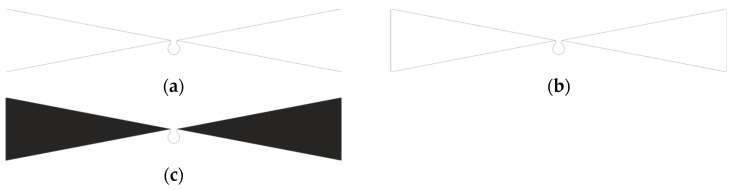
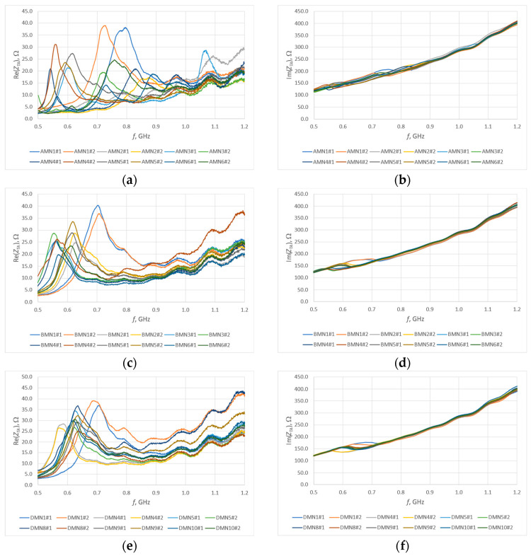
The production of consumer electronics using electrically conductive materials is a dynamically developing sector of the economy. E-textiles (electronic textiles) are also used in radio frequency identification technology, mainly in the production of tag antennas. For economic reasons, it is important that the finished product is universal, although frequencies in radio systems have different values in different regions of the world. Therefore, the antenna bandwidth must be sufficiently wide so that the read range of the tag is maximally large for all frequencies of the specified band. The bandwidth of an antenna depends on its type and geometric dimensions, but this parameter can also be influenced by the way a given type of antenna is made. The authors prepared samples of embroidered RFID tag antennas for the UHF band using various types of embroidery. Then, its impedance and the read range of the tag were examined in order to determine the exact influence of the type of embroidery on the parameter of interest (antenna bandwidth). The results obtained during the research indicate the influence of different embroidery styles is present; however, that influence is not significant.
Keywords: RFID transponder; embroidered antenna; embroidery; textile antenna; textronics.
Conflict of interest statement
The authors declare no conflicts of interest.
Figures


Similar articles
-
Textronic UHF RFID Transponder.Sensors (Basel). 2021 Feb 5;21(4):1093. doi: 10.3390/s21041093. Sensors (Basel). 2021. PMID: 33562566 Free PMC article.
-
The Influence of the Washing Process on the Impedance of Textronic Radio Frequency Identification Transponder Antennas.Materials (Basel). 2023 Jun 27;16(13):4639. doi: 10.3390/ma16134639. Materials (Basel). 2023. PMID: 37444952 Free PMC article.
-
Investigation of Factors Affecting the Performance of Textronic UHF RFID Transponders.Sensors (Basel). 2023 Dec 8;23(24):9703. doi: 10.3390/s23249703. Sensors (Basel). 2023. PMID: 38139549 Free PMC article.
-
MIMO Radio Frequency Identification: A Brief Survey.Sensors (Basel). 2022 May 28;22(11):4115. doi: 10.3390/s22114115. Sensors (Basel). 2022. PMID: 35684737 Free PMC article. Review.
-
A Review of Passive RFID Tag Antenna-Based Sensors and Systems for Structural Health Monitoring Applications.Sensors (Basel). 2017 Jan 29;17(2):265. doi: 10.3390/s17020265. Sensors (Basel). 2017. PMID: 28146067 Free PMC article. Review.
Cited by
-
Sensor Technologies for Non-Invasive Blood Glucose Monitoring.Sensors (Basel). 2025 Jun 7;25(12):3591. doi: 10.3390/s25123591. Sensors (Basel). 2025. PMID: 40573478 Free PMC article. Review.
References
-
- Younes B. Textronics: A Review of Their Technological Aspects and Applications. J. Text. Inst. 2024;115:1509–1525. doi: 10.1080/00405000.2023.2236320. - DOI
-
- Younes B. Smart E-Textiles: A Review of Their Aspects and Applications. J. Ind. Text. 2023;53:15280837231215493. doi: 10.1177/15280837231215493. - DOI
-
- Choudhry N.A., Arnold L., Rasheed A., Khan I.A., Wang L. Textronics—A Review of Textile-Based Wearable Electronics. Adv. Eng. Mater. 2021;23:2100469. doi: 10.1002/adem.202100469. - DOI
LinkOut - more resources
Full Text Sources
