

Metasurface higher-order poincaré sphere polarization detection clock
- PMID: 39863612
- PMCID: PMC11762790
- DOI: 10.1038/s41377-024-01738-1
Metasurface higher-order poincaré sphere polarization detection clock
Abstract
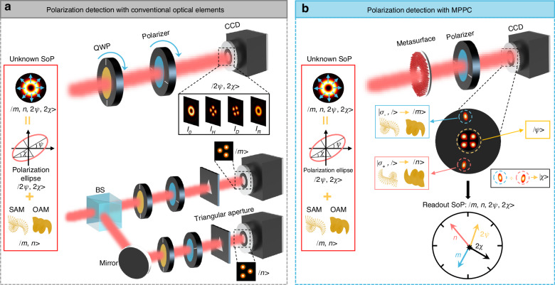
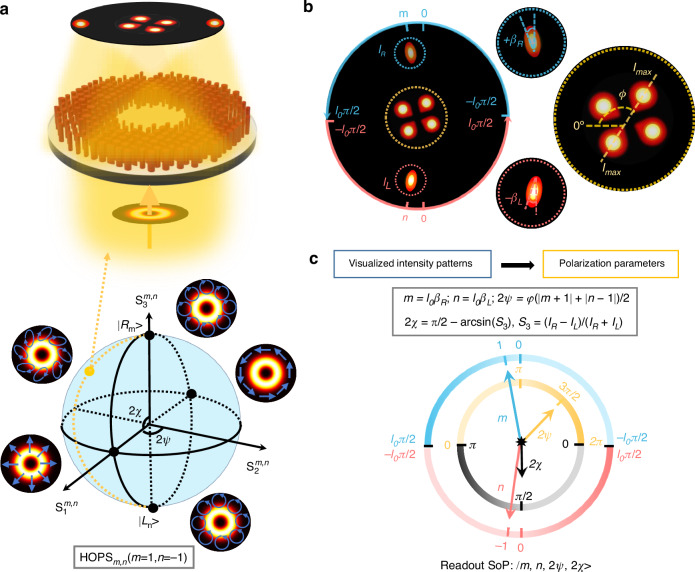
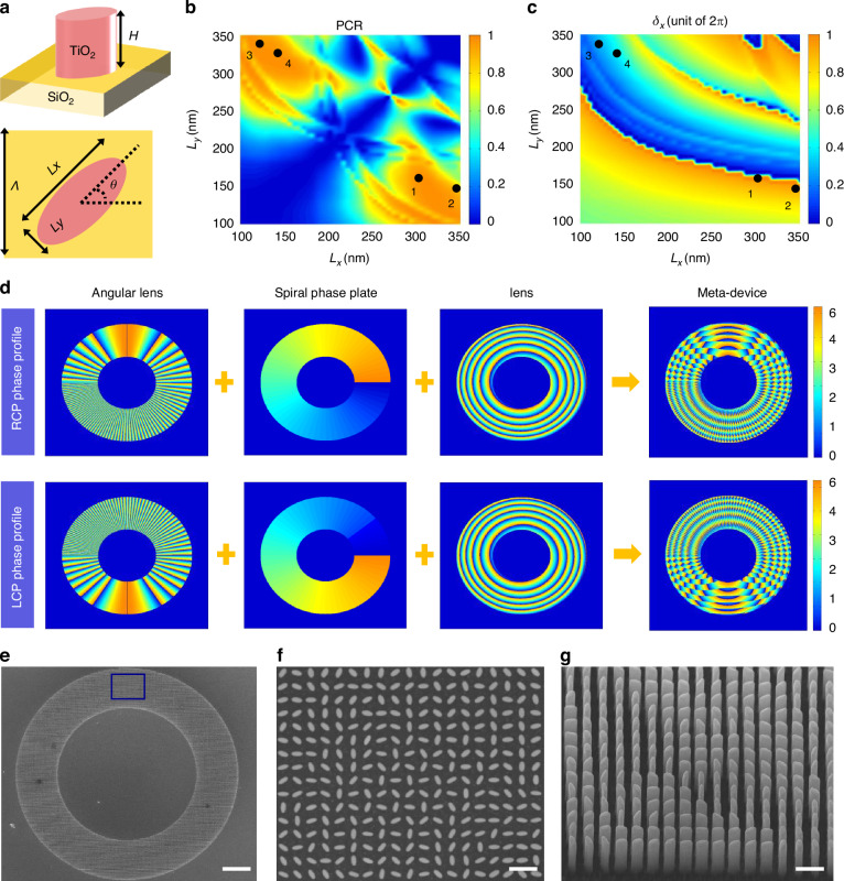
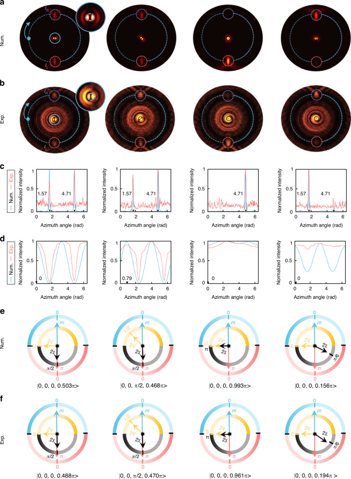
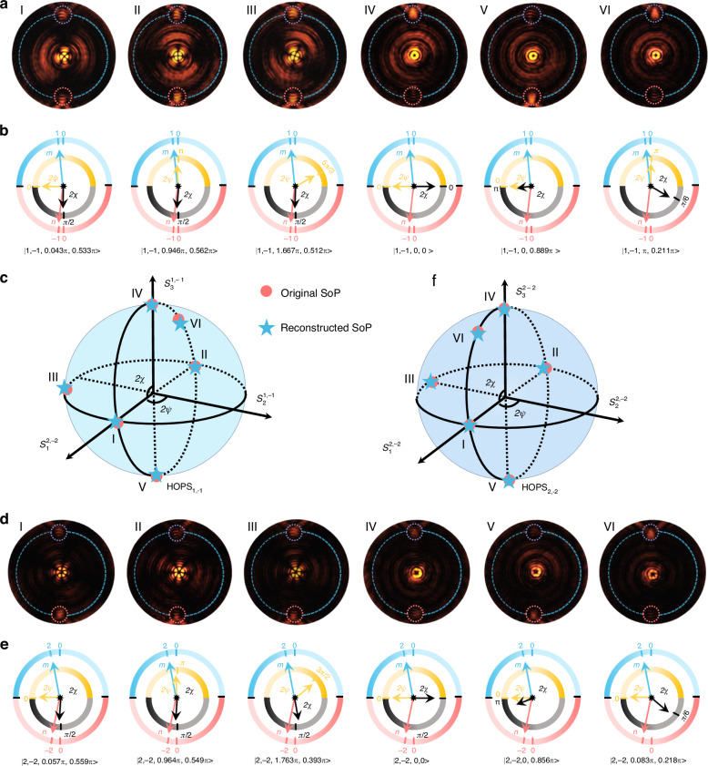
Accurately and swiftly characterizing the state of polarization (SoP) of complex structured light is crucial in the realms of classical and quantum optics. Conventional strategies for detecting SoP, which typically involves a sequence of cascaded optical elements, are bulky, complex, and run counter to miniaturization and integration. While metasurface-enabled polarimetry has emerged to overcome these limitations, its functionality predominantly remains confined to identifying SoP within the standard Poincaré sphere framework. The comprehensive detection of SoP on the higher-order Poincaré sphere (HOPS), however, continues to be a huge challenge. Here, we propose a general polarization metrology method capable of fully detecting SoP on any HOPS through a single measurement. The underlying mechanism relies on transforming the optical singularities and Stokes parameters into visualized intensity patterns, facilitating the extraction of all parameters that fully determine a SoP. We actualize this concept through a novel meta-device known as the metasurface photonics polarization clock, which offers an intuitive display of SoP using four distinct pointers. As a proof of concept, we theoretically and experimentally demonstrate fully resolving SoPs on the 0th, 1st, and 2nd HOPSs. Our implementation opens up a new pathway towards real-time polarimetry of arbitrary beams featuring miniaturized size, a simple detection process, and a direct readout mechanism, promising significant advancements in fields reliant on polarization.
© 2025. The Author(s).
Conflict of interest statement
Conflict of interest: The authors declare no competing interests.
Figures
Similar articles
-
Metasurface-Based Solid Poincaré Sphere Polarizer.Phys Rev Lett. 2023 Mar 24;130(12):123801. doi: 10.1103/PhysRevLett.130.123801. Phys Rev Lett. 2023. PMID: 37027878
-
All-dielectric geometric metasurfaces for the generation and manipulation of perfect high-order Poincaré sphere beams.Opt Lett. 2024 Mar 15;49(6):1599-1602. doi: 10.1364/OL.517089. Opt Lett. 2024. PMID: 38489460
-
Arbitrary polarization conversion dichroism metasurfaces for all-in-one full Poincaré sphere polarizers.Light Sci Appl. 2021 Jan 27;10(1):24. doi: 10.1038/s41377-021-00468-y. Light Sci Appl. 2021. PMID: 33504765 Free PMC article.
-
Polarization-analyzing circuit on InP for integrated Stokes vector receiver.Opt Express. 2017 May 29;25(11):12303-12310. doi: 10.1364/OE.25.012303. Opt Express. 2017. PMID: 28786588
-
Recent progress in metasurface-enabled optical waveplates.Nanophotonics. 2022 Apr 1;11(10):2219-2244. doi: 10.1515/nanoph-2022-0030. eCollection 2022 May. Nanophotonics. 2022. PMID: 39678086 Free PMC article. Review.
Cited by
-
Subwavelength imaging using orbital angular momentum waves generated by metasurfaces.Sci Rep. 2025 Jul 1;15(1):20539. doi: 10.1038/s41598-025-04813-8. Sci Rep. 2025. PMID: 40594175 Free PMC article.
References
-
- Poincaré, H. Théorie Mathématique de la Lumière (Gauthiers-Villars, 1892).
-
- Milione, G. et al. Higher-order Poincaré sphere, stokes parameters, and the angular momentum of light. Phys. Rev. Lett.107, 053601 (2011). - PubMed
-
- Naidoo, D. et al. Controlled generation of higher-order Poincaré sphere beams from a laser,. Nat. Photonics10, 327–332 (2016).
-
- Jiang, Z. H. et al. A single noninterleaved metasurface for high-capacity and flexible mode multiplexing of higher-order Poincaré sphere beams. Adv. Mater.32, 1903983 (2020). - PubMed
Grants and funding
- 62275078/National Natural Science Foundation of China (National Science Foundation of China)
- 12204165,62475069/National Natural Science Foundation of China (National Science Foundation of China)
- 62205250/National Natural Science Foundation of China (National Science Foundation of China)
- 52221001/National Natural Science Foundation of China (National Science Foundation of China)
- 2022JJ20020/Natural Science Foundation of Hunan Province (Hunan Provincial Natural Science Foundation)
LinkOut - more resources
Full Text Sources
Research Materials
