. 2025 Jan 11:31:101471.
doi: 10.1016/j.mtbio.2025.101471. eCollection 2025 Apr.

Filamented hydrogels as tunable conduits for guiding neurite outgrowth

Affiliations

Filamented hydrogels as tunable conduits for guiding neurite outgrowth

Hao Liu et al. Mater Today Bio. .

Abstract

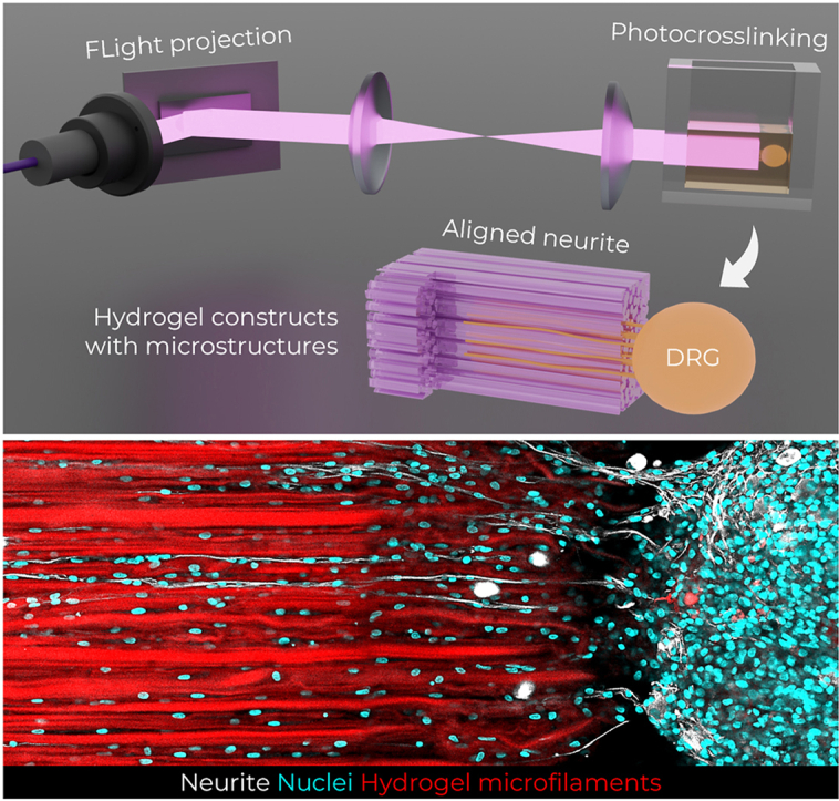
Anisotropic scaffolds with unidirectionally aligned fibers present an optimal solution for nerve tissue engineering and graft repair. This study investigates the application of filamented light (FLight) biofabrication to create hydrogel matrices featuring highly aligned microfilaments, facilitating neurite guidance and outgrowth from encapsulated chicken dorsal root ganglion (DRG) cells. FLight employs optical modulation instability (OMI) to rapidly and safely (<5 s) fabricate hydrogel constructs with precise microfilament alignment. The tunability of FLight matrices was demonstrated by adjusting four key parameters: stiffness, porosity, growth factor release, and incorporation of biological cues. Matrix stiffness was fine-tuned by varying the projection light dose, yielding matrices with stiffness ranging from 0.6 to 5.7 kPa. Optimal neurite outgrowth occurred at a stiffness of 0.6 kPa, achieving an outgrowth of 2.5 mm over 4 days. Matrix porosity was modified using diffraction gratings in the optical setup. While significant differences in neurite outgrowth and alignment were observed between bulk and FLight gels, further increases in porosity from 40 % to 70 % enhanced cell migration and axon bundling without significantly affecting maximal outgrowth. The incorporation of protein microcrystals containing nerve growth factor (NGF) into the photoresin enabled sustained neurite outgrowth without the need for additional NGF in the media. Finally, laminin was added to the resin to enhance the bioactivity of the biomaterial, resulting in a further increase in maximum neurite outgrowth to 3.5 mm after 4 days of culture in softer matrices. Overall, the varied matrix properties achieved through FLight significantly enhance neurite outgrowth, highlighting the importance of adaptable scaffold characteristics for guiding neurite development. This demonstrates the potential of FLight as a versatile platform for creating ideal matrices for clinical applications in nerve repair and tissue engineering.

Keywords: Dorsal root ganglion; Filamented light; Nerve growth factor; Neurite alignment.


Conflict of interest statement

The authors declare that they have no known competing financial interests or personal relationships that could have appeared to influence the work reported in this paper.

Figures

Image 1
Graphical abstract
Fig. 1
Fig. 1
Schematic illustration of the 3D FLight matrix with tunable properties guiding neurite alignment and growth. Filamented light projections are generated using a 405-nm diode laser and digital micromirror device (DMD). These shaped light beams are directly projected onto a quartz cuvette containing the photoresin and dorsal root ganglions (DRGs). Through optical modulation instability and self-focusing effects in the non-linear optical media, the intrinsic intensity distribution from the speckle pattern crosslinks the photoresin into hydrogel microfilaments, encapsulating DRGs within the 3D FLight hydrogel constructs. Channel-like void spaces form after removing uncrosslinked photoresin (below the solidification threshold), guiding neurite growth. The properties of the FLight matrices (e.g., stiffness, porosity) are tuned by applying different light doses or using different photomasks. The biochemical properties (e.g., neuron growth factor, bioactive molecules) are adjusted by loading varying concentrations of protein crystal cargo (PODS®) or laminin into the photoresin.
Fig. 2
Fig. 2
Matrix stiffness affecting neurite outgrowth in 3D FLight hydrogel. a) A 3D view of microstructures in different FLight hydrogel constructs printed with varying light doses. Scale bar: 100 μm. b) Quantitative analysis of hydrogels and microstructures, including the compressive modulus of hydrogel constructs tested parallel to the direction of microfilaments. Measurements of microstructures include the diameter of microfilaments and microchannels (n = 3, dataset size: 50), and the volume ratio of microchannels in the total 3D hydrogel volume (indicating hydrogel porosity). Numbers depict the mean value of microstructure dimensions. c) Representative confocal images of neurite growth in different FLight hydrogels after 4 days of culture. Blue dashed lines indicate the DRG body. The orientation map was generated from Tubulin Beta III (Tuj1) signals. Scale bar: 500 μm. d) Sholl analysis and alignment of neurites within FLight matrices with increased stiffness and reduced microchannel size (n = 3). (For interpretation of the references to colour in this figure legend, the reader is referred to the Web version of this article.)
Fig. 3
Fig. 3
Anisotropic microchannels in 3D FLight hydrogel guiding neurite outgrowth and alignment. a) A 3D view of microstructures in bulk and FLight hydrogel constructs printed using fluorescently labeled photoresin. Scale bar: 100 μm. b) Representative confocal images of neurite outgrowth in bulk and FLight hydrogel after 4 days of culture. The orientation map was generated from Tubulin Beta III (Tuj1) staining, indicating neurite alignment in the FLight matrix. Scale bar: 500 μm. c) Close-ups of neurite morphology in different 3D hydrogel matrices. Zoom-in views highlight growth cones (F-actin – purple). Scale bar: 500 μm. d) Zoom-in view of neurite outgrowth in filamented hydrogel matrix and cell infiltration between the fluorescently labeled microfilaments. Scale bar: 100 μm. e) Quantification of neurite outgrowth using Sholl analysis (n = 3). Distribution of neurite orientation between bulk and FLight hydrogel. The orientation angle was characterized by the angle deviation from the direction of light projection. (For interpretation of the references to colour in this figure legend, the reader is referred to the Web version of this article.)
Fig. 4
Fig. 4
Macrochannel architecture supporting neurite outgrowth and enhancing cell infiltration in 3D FLight hydrogel. a) A 3D view of microfilaments in FLight hydrogel constructs printed with different sizes of photomasks. Scale bar: 100 μm. Channel-like void spaces (macrochannels) were created in the FLight hydrogel in addition to microstructures. b) Quantification of hydrogel stiffness and evaluation of macro/microstructures in 3D hydrogel with different macrochannels (n = 3, dataset size: 50). Arrows highlight the diameter distribution of the channel-like structures, showing two clusters: microchannels with diameters less than 10 μm and macrochannels with diameters greater than 10 μm. The porosity was determined by the total ratio of channel structures, including macrochannels and microchannels, in the 3D hydrogel volume. Numbers depict the mean value of microstructure dimensions. c) Representative confocal images of neurite outgrowth in varying FLight hydrogels. Blue dashed lines highlight the DRG body. Close-ups of neurite-nuclei staining indicate the cell migration in FLight hydrogel. The orientation map was generated from Tubulin Beta III (Tuj1) images. Scale bar: 500 μm. d) Sholl analysis and alignment of neurite within FLight matrices with tuned macrochannels (n = 3). (For interpretation of the references to colour in this figure legend, the reader is referred to the Web version of this article.)
Fig. 5
Fig. 5
Locally-released growth factor supporting neurite growth in 3D FLight hydrogel. a) A 3D view of microfilaments and fluorescently labeled protein crystals (GFP-PODS) in FLight hydrogel constructs with different concentrations. Low: 0.33 million PODS/mL; Medium: 1.67 million PODS/mL; High: 8.3 million PODS/mL. Different amounts of cubic PODS microcrystals were homogeneously mixed with photoresin and encapsulated within the FLight matrix to release nerve growth factor (NGF) during culture. Scale bar: 50 μm. b) Quantification of the dimensions of microparticles and microstructures in 3D FLight hydrogel (n = 3, dataset size: 50). Numbers depict the mean value of microstructure dimensions. c) Representative confocal images of neurite growth in FLight hydrogels loaded with varying concentrations of NGF-PODS. Blue dashed lines indicate the DRG body. The orientation map was generated from Tubulin Beta III (Tuj1) images. Scale bar: 500 μm. d) Sholl analysis and alignment of neurites within PODS-laden FLight matrices (n = 3). (For interpretation of the references to colour in this figure legend, the reader is referred to the Web version of this article.)
Fig. 6
Fig. 6
Bioactive molecule supporting neurite outgrowth in 3D FLight hydrogel. a) Confocal images of laminin (LN) and microfilaments in 3D FLight matrices printed with different concentrations of LN. Low: 37.5 μg/mL; High: 75 μg/mL of LN in photoresins. Scale bar: 50 μm. b) Normalized fluorescent intensity of LN from confocal microscopic images (left), and quantification of the dimensions of microstructures in 3D FLight hydrogel (n = 3, dataset size: 50). Numbers depict the mean value of microstructure dimensions. c) Representative confocal images of neurite growth in FLight hydrogels loaded with varying concentrations of LN. Blue dashed lines indicate the DRG body. The orientation map was generated from Tubulin Beta III (Tuj1) images. Scale bar: 500 μm. d) Sholl analysis and alignment of neurite within LN-laden FLight matrices (n = 3). (For interpretation of the references to colour in this figure legend, the reader is referred to the Web version of this article.)

Similar articles

Cited by

References

    1. Sharifi M., Kamalabadi-Farahani M., Salehi M., Ebrahimi-Barough S., Alizadeh M. Recent advances in enhances peripheral nerve orientation: the synergy of micro or nano patterns with therapeutic tactics. J. Nanobiotechnol. 2024;22:1–29. doi: 10.1186/s12951-024-02475-8. - DOI - PMC - PubMed
    1. King R. Microscopic anatomy: normal structure. Handb. Clin. Neurol. 2013;115:7–27. doi: 10.1016/B978-0-444-52902-2.00002-3. - DOI - PubMed
    1. Pfister B.J., Gordon T., Loverde J.R., Kochar A.S., Mackinnon S.E., Kacy Cullen D. Biomedical engineering strategies for peripheral nerve repair: surgical applications, state of the art, and future challenges. Crit. Rev. Biomed. Eng. 2011;39:81–124. doi: 10.1615/CritRevBiomedEng.v39.i2.20. - DOI - PubMed
    1. Evans G.R.D. Peripheral nerve injury: a review and approach to tissue engineered constructs. Anat. Rec. 2001;263:396–404. doi: 10.1002/ar.1120. - DOI - PubMed
    1. Grinsell D., Keating C.P. Peripheral nerve reconstruction after injury: a review of clinical and experimental therapies. BioMed Res. Int. 2014;2014 doi: 10.1155/2014/698256. - DOI - PMC - PubMed

LinkOut - more resources