

Quantification of external disturbance forces in sliding microwire
- PMID: 39906847
- PMCID: PMC11791218
- DOI: 10.1016/j.heliyon.2025.e41990
Quantification of external disturbance forces in sliding microwire
Abstract
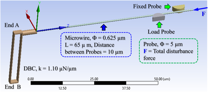
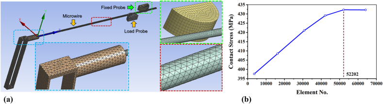
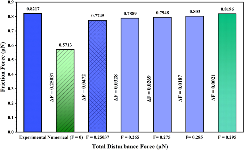
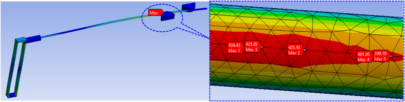
Due to microscale size and infinitesimal stiffness, the undesirable surface and external forces influence the mechanical behaviors of microstructures. It hinders MEMS functions, degrades reliability, and acts as a disturbance. Since MEMS functions based on microstructure mechanical behaviors, therefore, their quantification in microstructures is vital. However, the direct quantification is costly, difficult, and requires a controlled environment and unique experimental setups. Analytical assessment is also complex because of multi-physics involvement, nonlinearity of forces, and a lack of suitable mathematical models. Numerical analysis of microstructures is performed in the absence of all disturbance forces, whereas their influences cannot be eliminated during the experiment. This study aims to quantify the sum of disturbance forces in a microwire for the push-pull sliding motion against two opposite microprobes from the difference between experimental and numerical study and incorporating adhesive and electrostatic forces from literature for a single microprobe. The effect of the nonlinearity of surface forces is counted by iterating the initial difference of forces for which the numerically predicted contact force matches the experimental one. The sum of surface and external disturbance forces in the microwire is estimated to be 0.295 μN, including external disturbances of 0.177 μN. The predicted adhesive, electrostatic, and the sum of van der Waals, capillary, and hydrogen bonding forces are 0.118034, 0.02014, and 0.097894 μN, respectively. This study will help in quantifying disturbance forces in microstructures, like microbars, microrods, microplates, etc., and the appropriate design of MEMS devices.
Keywords: Adhesive force; Contact force; Disturbance force; MEMS devices; Microwire; Surface force.
© 2025 The Authors.
Conflict of interest statement
The authors declare that they have no known competing financial interests or personal relationships that could have appeared to influence the work reported in this paper.
Figures


References
-
- Rahman F., Akanda M.A.S. Numerical analysis of reaction forces at the supports of sliding microwire. J. Mech. Eng. Sci. 2020;14(4):7434–7445. doi: 10.15282/jmes.14.4.2020.12.0586. - DOI
-
- Shikida M., Hasegawa Y., Al Farisi M.S., Matsushima M., Kawabe T. Advancements in MEMS technology for medical applications: microneedles and miniaturized sensors. Jpn. J. Appl. Phys. 2022;61(SA):803. doi: 10.35848/1347-4065/ac305d. - DOI
-
- Rebello K.J. Applications of MEMS in surgery. Proc. IEEE. 2004;92(1):43–55. doi: 10.1109/JPROC.2003.820536. - DOI
-
- Ahmadi R., Kalantari M., Packirisamy M., Dargahi J. Modeling and optimal design of an optical MEMS tactile sensor for use in robotically assisted surgery. Photonics North. 2010;7750 doi: 10.1117/12.872025. 2010. - DOI
-
- Rahman F., Akanda M.A.S. Mechanical and dynamic characteristics of double and single beam cantilevers for MEMS manipulation. J. Mech. Sci. Technol. 2022;36(9):4635–4647. doi: 10.1007/s12206-022-0825-z. - DOI
LinkOut - more resources
Full Text Sources
