Review
. 2025 Feb 13;18(4):822.
doi: 10.3390/ma18040822.

Advanced Strategies for Enhancing the Biocompatibility and Antibacterial Properties of Implantable Structures

Affiliations
Review

Advanced Strategies for Enhancing the Biocompatibility and Antibacterial Properties of Implantable Structures

Oleg Mishchenko et al. Materials (Basel). .

Abstract

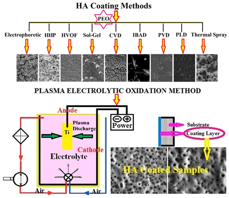
This review explores the latest advancements in enhancing the biocompatibility and antibacterial properties of implantable structures, with a focus on titanium (Ti) and its alloys. Titanium implants, widely used in dental and orthopedic applications, demonstrate excellent mechanical strength and biocompatibility, yet face challenges such as peri-implantitis, a bacterial infection that can lead to implant failure. To address these issues, both passive and active surface modification strategies have been developed. Passive modifications, such as altering surface texture and chemistry, aim to prevent bacterial adhesion, while active approaches incorporate antimicrobial agents for sustained infection control. Nanotechnology has emerged as a transformative tool, enabling the creation of nanoscale materials and coatings like TiO2 and ZnO that promote osseointegration and inhibit biofilm formation. Techniques such as plasma spraying, ion implantation, and plasma electrolytic oxidation (PEO) show promising results in improving implant integration and durability. Despite significant progress, further research is needed to refine these technologies, optimize surface properties, and address the clinical challenges associated with implant longevity and safety. This review highlights the intersection of surface engineering, nanotechnology, and biomedical innovation, paving the way for the next generation of implantable devices.

Keywords: antibacterial surfaces; bacterial contamination; biocompatibility; ion implantation; osseointegration; peri-implantitis; plasma electrolytic oxidation (PEO); surface modification; titanium implants.


Conflict of interest statement

The authors declare no conflicts of interest.

Figures

Figure 1
Figure 1
The conductivity of a 1.0 M Na2SiO3 electrolyte with varied concentration of silica sol at (a) 20 °C; (b) 60 °C. Reproduced with permission [207].
Figure 2
Figure 2
Schematic diagram of the uptake and incorporation mechanism of particles into PEO coating. Reproduced with permission [212].
Figure 3
Figure 3
Zeta potentials of ZrO2 and TiO2 powders at different pH levels in alkaline fluoride-based electrolyte. Reproduced with permission [222].
Figure 4
Figure 4
Apatite-forming ability of (a) PEO and (b) PEO incorporated with particles after immersion in SBF for 3 days. Reproduced with permission [256].
Figure 5
Figure 5
SEM top and cross-sectional view and EDS spectroscopy of the PEO fabricated at different times ((a,a”) 2, (b,b”) 4, and (c,c”) 6 min). Reproduced with permission [306].
Figure 6
Figure 6
Uncoated Ti cp with colorless native oxide film, from blue to green, the electric-potential-dependent anodic pre-spark films, and the gray surface of an anodic spark-discharge-generated coating (left to right). Reproduced with permission [319].
Figure 7
Figure 7
(A) Visible micro plasma sparking at a Ti dental implant as an anode during ASD. (B) Anodic pre-spark conversion film (left) and the initial state of the ASD process of a Ti surface with first spark-discharge-generated molten oxide traces (right) because of the spark avalanches. Reproduced with permission [317].
Figure 8
Figure 8
Preparation of Ticer using anodic spark deposition: (A) electrolyte cell and ASD process on anode; (B) surface upon treatment (SEM and schematic representation). Reproduced with permission [317].
Figure 9
Figure 9
SEM of non-porous (control) and porous surfaces (PA, SA, and Ca). Reprinted and adapted from [331], Copyright 2003, with permission from Elsevier.
Figure 10
Figure 10
The surface of layers of self-aligned TiO2 nanotubes have different pore sizes (between 15 and 100 nm). Self-assembled layers of vertically oriented TiO2 nanotubes were generated by anodizing titanium sheet. Reproduced with permission [105,341].
Figure 11
Figure 11
Some newly developed titanium-based implant surfaces prepared using different electrolyte systems (upper—two white surfaces (Ticer white); lower—two zirconia-coated Ti cp surfaces). Reproduced with permission [317,350].
Figure 12
Figure 12
SEM micrographs of as-manufactured (I, II), 2 min (III), and 5 min (IV) PEO-treated scaffolds (AD). Reproduced with permission [263].
Figure 13
Figure 13
SEM images (af) of the oxide layer on AJ62 during various PEO (MAO) treatment times. Reproduced with permission [362].
Figure 14
Figure 14
SEM view of the structured layer at 480 V treated for (A) 1.5, (B) 3, (C) 10, and (D) 20 min via the oxidation process (MAO). Reproduced with permission [363].
Figure 15
Figure 15
SEM images of different HA structures after MAO hydrothermal treatment for 6 h ((a) 150 °C, (b) 200 °C, and (c) 250 °C, (d) 250 °C—6 h in 100 mL solution, (e) 250 °C—6 h in 400 mL solution; (f) 250 °C—12 h in 200 mL solution). Reproduced with permission [367].
Figure 16
Figure 16
The surface SEM micrographs of PEO-coated pure zirconium for the period of (a) 5 min, (b) 10, (c) 20, (d) 30, (e) 45, (f) 60, (g) 90, and (h) 120 min, successively. Reproduced with permission [370].
Figure 17
Figure 17
The high magnification of a typical SEM image of the equiaxed cluster is taken from Figure 16f (marked as “M”) for the process time of 60 min: (a) 4000× and (b) 16,000×. Reproduced with permission [370].
Figure 18
Figure 18
Typical SEM images from the surface: (a) the coating flakes off from the surface of Figure 16h (marked as “N”) with higher magnification; and (b) the presence of very fine equiaxed crystals just underneath the smooth regions around the plasma channel openings. Reproduced with permission [370].
Figure 19
Figure 19
FESEM images of the layer grown in an electrolyte containing 5 g/L calcium acetate and 5 g/L β-glycerophosphate for 3 min (a) and cross-section of the two-layer interface (b). Reproduced with permission [307].
Figure 20
Figure 20
FE-SEM images show PEO-treated film surfaces of (a) Z0, (b) Z5, (c) Z10, and (d) Z20 specimens. Reproduced with permission [376].
Figure 21
Figure 21
FE-SEM images showing the morphology of bone-like apatite: (a) Z0, (b) Z0 (magnified—a), (c) Z5, (d) Z5 (magnified—c), (e) Z10, (f) Z10 (magnified—e), and (g) Z20, (h) Z20 (magnified—g). Reproduced with permission [376].
Figure 22
Figure 22
SEM micrographs of the samples after the PEO treatment: general view of the surface (a), porous structure of the surface (b), interconnecting pores (c), and HA nanoparticle agglomerates on the porous surface (d). Reproduced with permission [385].
Figure 23
Figure 23
Schematic view of the SPD process. Reproduced with permission [414].
Figure 24
Figure 24
Schematic view of bonding hydroxyapatite on the titanium surface. Reproduced with permission [415].
Figure 25
Figure 25
Schematic view of various HAp nanostructures. Reproduced with permission [417].
Figure 26
Figure 26
Morphology of the HA layer via different coating methods and schematic view of the PEO method. Reproduced with permission [419].

Similar articles

Cited by

References

    1. Zhang L., Liao X., Fok A., Ning C., Ng P., Wang Y. Effect of Crystalline Phase Changes in Titania (TiO2) Nanotube Coatings on Platelet Adhesion and Activation. Mater. Sci. Eng. C. 2018;82:91–101. doi: 10.1016/j.msec.2017.08.024. - DOI - PubMed
    1. Mishchenko O., Solodovnik O., Oleshko O. Osteointegration of Dental Implants with Different Surface Types. Bukovinian Med. Bull. 2020;24:79–89. doi: 10.24061/2413-0737.XXIV.1.93.2020.11. - DOI
    1. Mouhyi J., Dohan Ehrenfest D.M., Albrektsson T. The Peri-Implantitis: Implant Surfaces, Microstructure, and Physicochemical Aspects. Clin. Implant Dent. Relat. Res. 2012;14:170–183. doi: 10.1111/j.1708-8208.2009.00244.x. - DOI - PubMed
    1. Carmona G., Rodriguez A., Juarez D., Corzo G., Villegas E. Improved Protease Stability of the Antimicrobial Peptide Pin2 Substituted with D-Amino Acids. Protein J. 2013;32:456–466. doi: 10.1007/s10930-013-9505-2. - DOI - PubMed
    1. Smeets R., Henningsen A., Jung O., Heiland M., Hammächer C., Stein J.M. Definition, Etiology, Prevention and Treatment of Peri-Implantitis—A Review. Head Face Med. 2014;10:34. doi: 10.1186/1746-160X-10-34. - DOI - PMC - PubMed

LinkOut - more resources