Review
. 2025 Feb 27;19(1):011502.
doi: 10.1063/5.0236911. eCollection 2025 Jan.

Microfluidics for the biological analysis of atmospheric ice-nucleating particles: Perspectives and challenges

Affiliations
Review

Microfluidics for the biological analysis of atmospheric ice-nucleating particles: Perspectives and challenges

Mark D Tarn et al. Biomicrofluidics. .

Abstract

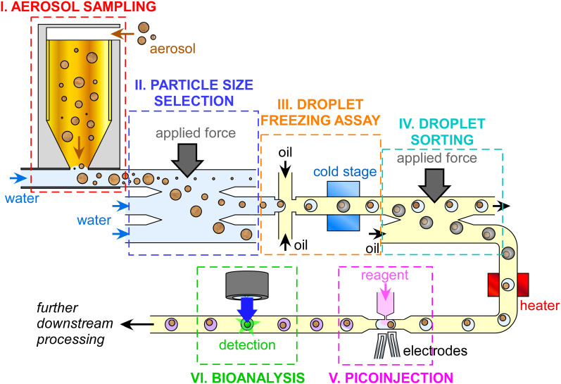
Atmospheric ice-nucleating particles (INPs) make up a vanishingly small proportion of atmospheric aerosol but are key to triggering the freezing of supercooled liquid water droplets, altering the lifetime and radiative properties of clouds and having a substantial impact on weather and climate. However, INPs are notoriously difficult to model due to a lack of information on their global sources, sinks, concentrations, and activity, necessitating the development of new instrumentation for quantifying and characterizing INPs in a rapid and automated manner. Microfluidic technology has been increasingly adopted by ice nucleation research groups in recent years as a means of performing droplet freezing analysis of INPs, enabling the measurement of hundreds or thousands of droplets per experiment at temperatures down to the homogeneous freezing of water. The potential for microfluidics extends far beyond this, with an entire toolbox of bioanalytical separation and detection techniques developed over 30 years for medical applications. Such methods could easily be adapted to biological and biogenic INP analysis to revolutionize the field, for example, in the identification and quantification of ice-nucleating bacteria and fungi. Combined with miniaturized sampling techniques, we can envisage the development and deployment of microfluidic sample-to-answer platforms for automated, user-friendly sampling and analysis of biological INPs in the field that would enable a greater understanding of their global and seasonal activity. Here, we review the various components that such a platform would incorporate to highlight the feasibility, and the challenges, of such an endeavor, from sampling and droplet freezing assays to separations and bioanalysis.


Conflict of interest statement

The authors have no conflicts to disclose.

Figures

FIG. 1.
FIG. 1.
An idealized example of a sample-to-answer microfluidic platform for the sampling and analysis of biological ice-nucleating particles (INPs) incorporating all of the major processes, including (i) aerosol samplng, (ii) particle size separation and selection, (iii) droplet freezing assay (DFA) for INP quantification, (iv) separation of frozen and unfrozen droplets, (v) picoinjection of biochemical reagents into droplets, and (vi) bioanalytical identification and quantification of biological species via methods such as immunoassays or DNA analysis.
FIG. 2.
FIG. 2.
Traditional aerosol sampling techniques that have been employed for the microfluidic analysis of INPs. (a) Filter sampling, in which aerosols are pulled through a filter for the collection of particles, which are subsequently washed off the filter and into an aqueous suspension for analysis. Filter sampling is discussed further in Sec. II A. (b) A cascade impactor, in which aerosols pass through a series of nozzles and aerosols of differing size impact upon different collection plates. A three-stage impactor is shown. Plates (often small-pore filters) are then washed into aqueous suspension for analysis. Cascade impactors are discussed further in Sec. II C. (c) A wet cyclone sampler that pulls aerosols directly into water circulating within a vial, allowing a direct analysis of the aqueous suspension. Impingers are similar instruments in which air is bubbled into water, allowing transfer of the aerosols from the gas phase and into the aqueous phase (e.g., Greenburg–Smith bubble impingers). Wet cyclones are discussed further in Sec. II E.
FIG. 3.
FIG. 3.
Various miniaturized aerosol sampling techniques that have been developed to collect aerosol particles directly into aqueous suspensions in microfluidic platforms. (a)–(c) Examples of the “droplet sweeping” technique for the collection of aerosols into a droplet, upon prior sampling of the aerosols onto a microfabricated filter or a flat substrate. (a) A microfabricated membrane filter, with a droplet actuated by oscillating pressure to drive the air–liquid interface over the region of captured droplets. (b) Principle of electrowetting-on-dielectric (EWOD), in which droplets can be moved across arrays of electrodes, to sweep up collected particles. Adapted and used with permission from Zhao and Cho, Lab Chip 6, 137–144 (2006). Copyright 2006 Royal Society of Chemistry, permission conveyed through Copyright Clearance Center, Inc. (c) Surface acoustic waves (SAWs) applied via transducers to generate recirculating flows in a droplet to sweep up particles. Adapted and used with permission from Tan et al., Lab Chip 7, 618–625 (2007). Copyright 2007 Royal Society of Chemistry, permission conveyed through Copyright Clearance Center, Inc. (d) Microelectromechanical systems (MEMS)-based virtual impactors (VIs). Reprinted with permission from Kim et al., Appl. Phys. Lett. 91, 043512 (2007). Copyright 2007 AIP Publishing LLC. (e) An aerodynamic lens (ADL) that directs a narrow band of aerosol into a pinned droplet. Adapted and used with permission from Damit et al., Aerosol Sci. Technol. 51, 488–500 (2017), reprinted by permission of the publisher (Taylor & Francis Ltd, http://www.tandfonline.com). (f) A curved microfluidic impinger that employs Dean forces to continuously transfer aerosols into water. Reprinted (adapted) with permission from Choi et al., ACS Sensors 2, 513–521 (2017). Copyright 2017 American Chemical Society. (g) A microfluidic Greenburg–Smith impinger in which bubbles of aerosol are generated in liquid for their transfer into aqueous suspension. Adapted and used with permission from Mirzaee et al., Lab Chip, 16, 2254–2264 (2016). Copyright 2016 Royal Society of Chemistry, permission conveyed through Copyright Clearance Center, Inc. (h) A traditional condensation growth tube collector integrated with a microfluidic device. Reprinted (adapted) with permission from Noblitt et al., Anal. Chem. 81, 10029–10037 (2009). Copyright 2009 American Chemical Society. (i) A microfluidic condensational growth chip. Adapted and used with permission from Kwon et al., Lab Chip 19, 1471–1483 (2019). Copyright 2019 Royal Society of Chemistry, permission conveyed through Copyright Clearance Center, Inc. (j) An electrostatic precipitator (ESP) with a removable collection slide that can be subjected to droplet sweeping particle collection, e.g., via EWOD. (k) An integrated microfluidic electrostatic sampler (IMES). Adapted and used with permission from Ma et al., J. Aerosol Sci. 95, 84–94 (2016). Copyright 2016 Elsevier. (l) An aerosol-to-hydrosol sampler employing ESP. Adapted and used with permission from Park et al., Anal. Chim. Acta 941, 101–107 (2016). Copyright 2016 Elsevier. (m) Staggered herringbone mixer (SHM) micropatterned grooves in a microfluidic device that generate chaotic flows for the capture of aerosol in the grooves, allowing them to be washed into aqueous suspension. Reprinted (adapted) with permission from Jing et al., Anal. Chem. 85(10), 5255–5262 (2013). Copyright 2013 American Chemical Society.
FIG. 4.
FIG. 4.
Principle of on-chip continuous flow size-based particle separations. Typically, a lateral force is applied to particles flowing across a microfluidic chamber, with different sized particles interacting with the force to differing extents. This allows some particles to migrate further in the lateral direction than others, enabling their collection via different outlet channels. Forces that can be utilized to induce the lateral flow include acoustic, magnetic, electric (e.g., dielectrophoretic), and hydrodynamic, or the use of pillars and barriers in the flow stream.
FIG. 5.
FIG. 5.
The use of microfluidically generated droplet emulsions for droplet freezing assays (DFAs). Water-in-oil droplets are typically generated in a (a) T-junction or (b) flow focusing channel configuration and collected off-chip in a vial. (c) The droplet emulsion can then be pipetted onto a glass slide on a cold stage and cooled until all of the droplets have frozen. The temperatures at which the droplets freeze reveal information on the concentration and activity (e.g., ice active site density per mass or surface area) of the INPs. A transparent lid is usally placed atop the droplet suspension during freezing (not shown for clarity) to prevent evaporation.
FIG. 6.
FIG. 6.
Microfluidic droplet array techniques for on-chip microfluidic DFAs, in which an array generated on a substrate is cooled to freezing temperatures. (a) Dropspots array technique, utilized also in the WISDOM and nanoBINARY DFA methods. Adapted and used with permission from Schmitz et al., Lab Chip 9, 44–49 (2009). Copyright 2009 Royal Society of Chemistry, permission conveyed through Copyright Clearance Center, Inc. (b) A bypass trap array for the exchange of the medium around frozen droplets, located in a helium cooled chamber. Adapted and used with permission from Sgro and Chiu, Lab Chip 10, 1873–1877 (2010). Copyright 2010 Royal Society of Chemistry, permission conveyed through Copyright Clearance Center, Inc. (c) “Freeze-on-a-chip” ceiling array that relies on a high density oil to trap aqueous droplets in ceiling wells. Adapted and used with permission from Weng et al., Cryobiology 84, 91–94 (2018). Copyright 2018 Elsevier. (d) “Store and create” droplet array, in which water is flushed through a channel then flushed with oil (or backflushed with oil or gas) to leave droplets in traps, eliminating the need for surfactants as in many other techniques. Adapted and used with permission from Brubaker et al., Aerosol Sci. Technol. 54, 79–93 (2020), reprinted by permission of the publisher (Taylor & Francis Ltd, http://www.tandfonline.com). (e) Piezoeletric transducer actuated droplet printer used to automatically print a droplet array on a substrate on a motorised stage. (f) Microcavity-based “Freezing on a Chip” platform in which microcavities in a gold or gold-coated substrate are used to generate droplets in an array for freezing. (g) Nanoliter osmometer adapted for DFAs via the microinjection of droplets into oil-filled wells in a silver grid. (h) Millifluidic spiral tubing-based array on a cold plate. (i) Microfluidic serpentine tubing-based droplet array in a chilled bath.
FIG. 7.
FIG. 7.
Continuous flow microfluidic DFAs, in which droplets are generated and then freeze as they pass over a cold stage, allowing the analysis of thousands of droplets. (a) Use of a multi-cold stage instrument to generate a defined temperature gradient. The position at which a droplet freezes thus indicates the temperature at which it froze. (b) Use of a single cold plate, in which the relative number of frozen and unfrozen droplets are counted over a series of set temperatures of the stage, as used in the LOC-NIPI platform. Adapted from Tarn et al., Lab Chip 20, 2889–2910 (2020). Copyright 2020, Author(s) licensed under a Creative Commons Attribution 3.0 Unported License.
FIG. 8.
FIG. 8.
The sorting of frozen and unfrozen droplets for the later analysis and comparison of the two populations, based on the greater density of water to ice. (a) Freeze-float sorting in a cuvette in a non-microfluidic method, utilizing oils of differing densities to generate cushion and buoyancy layers. Reprinted (adapted) with permission from Kamijo and Derda, Langmuir 35, 359–364 (2019). Copyright 2019 American Chemical Society. (b) Microfluidic continuous flow sorting of frozen and unfrozen droplets based on their relative buoyancies under gravity, allowing the collection of the two populations via different outlets, as used in the LOC-NIPI platform. Adapted from Porter et al., Lab Chip 20, 3876–3887 (2020) Copyright 2020, Author(s) licensed under a Creative Commons Attribution 3.0 Unported License.
FIG. 9.
FIG. 9.
Picoinjection of biochemical reagents into droplets as they flow past a narrow channel picoinjector. Reprinted (adapted) with permission from Abate et al., Proc. Natl. Acad. Sci. U. S. A. 107, 19163–19166 (2010). Copyright 2010 National Academy of Sciences. The interface between the aqueous droplet and the surrounding immiscible oil is momentarily perturbed, allowing injection. The perturbation is often achieved by applying an electric field via microelectrodes, though the use of controlled pressure or the Venturi effect can also be applied. Picoinjection of reagents can allow downstream biochemical analysis to be performed, such as single cell analyses, immunoassays, or DNA analysis.

References

    1. Vali G., Bull. Am. Meteorol. Soc. 56(11), 1180–1184 (1975). 10.1175/1520-0477-56.11.1180 - DOI
    1. Jiusto J. E. and Lavoie R. L., Bull. Am. Meteorol. Soc. 56(11), 1175–1179 (1975). 10.1175/1520-0477-56.11.1175 - DOI
    1. Kanji Z. A., Ladino L. A., Wex H., Boose Y., Burkert-Kohn M., Cziczo D. J., and Krämer M., Meteorol. Monogr. 58, 1.1–1.33 (2017). 10.1175/AMSMONOGRAPHS-D-16-0006.1 - DOI
    1. Murray B. J., O'Sullivan D., Atkinson J. D., and Webb M. E., Chem. Soc. Rev. 41(19), 6519–6554 (2012). 10.1039/c2cs35200a - DOI - PubMed
    1. Murray B. J., Carslaw K. S., and Field P. R., Atmos. Chem. Phys. 21(2), 665–679 (2021). 10.5194/acp-21-665-2021 - DOI

LinkOut - more resources