. 2025 Mar 5;4(1):41.
doi: 10.1038/s44172-025-00371-z.

Additive manufacturing of a 3D-segmented plastic scintillator detector for tracking and calorimetry of elementary particles

Affiliations

Additive manufacturing of a 3D-segmented plastic scintillator detector for tracking and calorimetry of elementary particles

Tim Weber et al. Commun Eng. .

Abstract

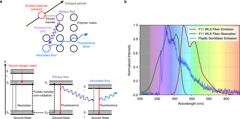
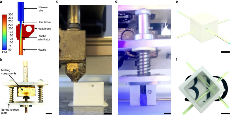
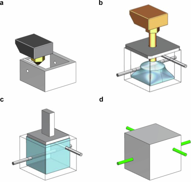
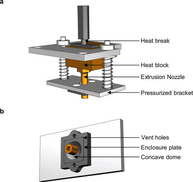
Plastic scintillators, segmented into small, optically isolated voxels, are used for detecting elementary particles and provide reliable particle identification with nanosecond time resolution. Building large detectors requires the production and precise alignment of millions of individual units, a process that is time-consuming, cost-intensive, and difficult to scale. Here, we introduce an additive manufacturing process chain capable of producing plastic-based scintillator detectors as a single, monolithic structure. Unlike previous manufacturing methods, this approach consolidates all production steps within one machine, creating a detector that integrates and precisely aligns its voxels into a unified structure. By combining fused deposition modeling with an injection process optimized for fabricating scintillation geometries, we produced an additively manufactured fine-granularity plastic scintillator detector with performance comparable to the state of the art, and demonstrated its capabilities for 3D tracking of elementary particles and energy-loss measurement. This work presents an efficient and economical production process for manufacturing plastic-based scintillator detectors, adaptable to various sizes and geometries.


Conflict of interest statement

Competing interests: The authors declare no competing interests.

Figures

Fig. 1
Fig. 1. Scintillation process
Absorption and emission spectra of detector components (a) in a plastic scintillator matrix, doped with primary and secondary fluors, the scintillation process is initiated when a charged particle passes through the material. b Emission spectrum in blue of a 3D-printed plastic scintillator sample recorded with a spectrophotometer, absorption spectrum in green, and emission spectrum in red of a Kuraray Y11 wavelength-shifting fiber. The background color represents the light’s color as a function of wavelength.
Fig. 2
Fig. 2. Manufacturing process of an optically isolated plastic scintillator voxel.
a CFD result of the injection system at an extrusion speed of 15 mm s−1. Flow direction from top to bottom. The color scheme represents the temperature in °C at specific locations in the extrusion system. b Injection system used to form PS within an FDM-fabricated reflective frame. Scale bar, 6.5 mm. c FDM fabrication of a reflective frame with holes for the positioning and insertion of WLS fibers. Scale bar, 3 mm. d Forming of PS volume. To better visualize the flow of melted PS, the sample was illuminated with UV light, and the cavity was opened to provide a clear view. Scale bar, 3 mm. e Completed optically isolated PS voxel equipped with WLS fibers. Scale bar, 6 mm. f A voxel without top and bottom layer. The bottom face of the PS was polished to remove the surface roughness left by the FDM-fabricated mold during the injection process, allowing the transparency of the scintillator to be showcased. Scale bar, 3 mm.
Fig. 3
Fig. 3. Light transmittance of the reflector material.
Light transmittance measurements of white reflector sheets with a thickness of 1 mm. Bottom and top walls in the SuperCube were built horizontally, side walls were built vertically.
Fig. 4
Fig. 4. FIM-fabricated SuperCube.
a The fifth layer of the SuperCube, unsealed and illuminated with UV light, showcasing the active PS volume within each voxel and the WLS fibers extending through the entire detector. Scale bar, 14 mm. b Completed FIM-manufactured 5 × 5 × 5 voxel SuperCube. Scale bar, 15 mm.
Fig. 5
Fig. 5. Cosmic particle tracking.
a FIM-manufactured SuperCube instrumented with WLS fibers and silicon photomultipliers in the X and Y directions. Scale bar 10 mm. b Path reconstruction of a cosmic particle traversing the SuperCube along a vertical trajectory. c Path reconstruction of a cosmic particle traversing the SuperCube along a diagonal trajectory. In both (b) and (c), the grid in the X, Y, and Z directions represents the voxels within the SuperCube, while the color scheme in the 2D projections represents the measured light yield in units of photoelectrons detected in each readout channel.
Fig. 6
Fig. 6. SuperCube performance.
a Scintillation light yield distribution across all voxels in the SuperCube in blue, and the cast polymerization layer (C.P. layer) in orange. b Scintillation light cube-to-cube crosstalk distribution throughout the entire SuperCube in blue and the cast polymerization layer in orange. Both, in (a) and (b), the values were normalized to the number of events recorded during the measurement period.
Fig. 7
Fig. 7. SuperCube geometry.
a Components of a voxel with sections of the reflective frame cut away on the top and side. The reflective shell in white encloses the cube-shaped PS in blue, which is traversed by two wavelength-shifting fibers in green positioned at their respective coordinates in millimeters. b Depiction of a 5 × 5 × 5 voxel SuperCube with its outer dimensions in millimeters.
Fig. 8
Fig. 8. Depiction of the FIM fabrication process.
a Reflective frame fabrication via fused deposition modeling. b Plastic scintillator forming using a customized extrusion setup. Metal rods in black create circular voids for wavelength-shifting fiber insertion. The pressurized bracket on top of the voxel constrain the melt pool within the cavity. c Planing of the top surface using a heated punch. d A completed voxel with wavelength-shifting fibers in green inserted through the whole structure.
Fig. 9
Fig. 9. FIM injection components.
a Depiction of the extrusion system components modified for the filling of scintillation material into the reflective cavity. b Geometry of the pressurized plate that is pressed onto the cavity to keep the melt pool restrained in fill volume.
Fig. 10
Fig. 10. CFD analysis setup.
a Extrusion components of the CFD model. Each component is assigned a unique color, while the black mesh represents the discretization points of the structure. b Cross-sectional view of the interior of the model, depicting the polyhedral volume mesh.

References

    1. Schorr, M. G. & Torney, F. L. Solid non-crystalline scintillation phosphors. Phys. Rev.80, 474–474 (1950).
    1. Amaudruz, P.-A. et al. The T2K fine-grained detectors. Nucl. Instrum. Meth. A696, 1–31 (2012).
    1. Aliaga, L. et al. Design, calibration, and performance of the MINERvA detector. Nucl. Instrum. Meth. A743, 130–159 (2014).
    1. Michael, D. G. et al. The Magnetized steel and scintillator calorimeters of the MINOS experiment. Nucl. Instrum. Meth. A596, 190–228 (2008).
    1. Joram, C. et al. LHCb Scintillating Fibre Tracker Engineering Design Review Report: Fibres, Mats and Modules. Tech. Rep. https://cds.cern.ch/record/2004811 (CERN, Geneva, 2015).

LinkOut - more resources