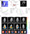
. 2024 Dec;1(1):13-34.
doi: 10.53941/mi.2024.100004. Epub 2024 Nov 21.

Emerging Piezoelectric Metamaterials for Biomedical Applications

Affiliations

Emerging Piezoelectric Metamaterials for Biomedical Applications

Zishuo Yan et al. Mater Interfaces. 2024 Dec.

Abstract

Emerging piezoelectric metamaterials hold immense promise for biomedical applications by merging the intrinsic electrical properties of piezoelectricity with the precise architecture of metamaterials. This review provides a comprehensive overview of various piezoelectric materials- such as molecular crystals, ceramics, and polymers-known for their exceptional piezoelectric performance and biocompatibility. We explore the advanced engineering approaches, including molecular design, supramolecular packing, and 3D assembly, which enable the customization of piezoelectric properties for targeted biomedical applications. Particular attention is given to the pivotal role of metamaterial structuring in the development of 0D spheres, 1D fibers and tubes, 2D films, and 3D scaffolds. Key biomedical applications, including tissue engineering, drug delivery, wound healing, and biosensing, are discussed through illustrative examples. Finally, the article addresses critical challenges and future directions, aiming to drive further innovations in piezoelectric biomaterials for next-generation healthcare technologies.

Keywords: 3D assembly; biomedical applications; molecular design; piezoelectric metamaterials; supramolecular packing.


Conflict of interest statement

Conflicts of Interest: The authors declare no competing financial interest.

Figures

Figure 1.
Figure 1.
Schematic illustration of the overview of this work. Piezoelectric materials can be designed in different dimensional forms (e.g., 0D spheres, 1D fibers and tubes, 2D films, and 3D scaffolds) with their piezoelectric properties being tunable by controlling crystal orientation, structure design, and 3D assembly. This versatility allows for potential applications in biomedical fields including tissue engineering, drug delivery, wound healing, and biosensing. Tissue engineering: Reproduced with permission [39]. Copyright 2024, The American Association for the Advancement of Science. Drug delivery: Reproduced with permission [40]. Copyright 2024, Elsevier. Wound healing: Reproduced with permission [41]. Copyright 2023, Elsevier. Sensor and 2D films: Reproduced with permission [42]. Copyright 2024, The American Association for the Advancement of Science. 0D spheres: Reproduced with permission [43]. Copyright 2023, Wiley. 1D fibers: Reproduced with permission [44]. Copyright 2023, The American Association for the Advancement of Science. 1D tubes: Reproduced under the terms of the CC BY license [45]. Copyright 2019, Authors, published by AIP Publishing. Wood sponge: Reproduced with permission [46]. Copyright 2020, American Chemical Society. 3D scaffolds with Rochelle salt: Reproduced with permission [47]. Copyright 2023, Springer Nature. Piezoelectric effect: Reproduced with permission [48]. Copyright 2018, American Chemical Society.
Figure 2.
Figure 2.
Glycine-based piezoelectric materials. (a) Schematic diagram and (b) contour plot of charge density distribution of γ-glycine molecules. (c) Piezoelectric constants of γ-glycine. (d) Orientation dependence of d33,eff. (e) The piezoelectric effect of γ-glycine induced by the hydrogen bonding interactions. (f) The fabrication process of γ-glycine/PVA films. (g) Optical photographs of the flexible γ-glycine/PVA films. The inset shows the twisted films. Scale bars, 10 mm. (h) Voltage output of glycine/PVA films. (ah) Reproduced with permission [58]. Copyright 2024, The American Association for the Advancement of Science. (i) SEM images of PCL (top) and glycine-PCL (bottom) fibers. (j) Displacement of solvent-casting, random electrospinning, and aligned electrospinning films. (ij) Reproduced with permission [44]. Copyright 2023, The American Association for the Advancement of Science.
Figure 3.
Figure 3.
Ceramic-based piezoelectric materials. (a) The fabrication process of the Janus piezoelectric nanofibrous scaffolds. (b) The optical photographs of the OPZ/RPB scaffold. (c) The SEM images of the OPZ/RPB scaffold. (d) Voltage output of the scaffolds under an external periodic impact force (20 kPa, 1 Hz). (e) Voltage output of the OPZ/RPB scaffold under slight finger tapping. (f) The maintenance of the piezoelectric output during the degradation period. (g) The mechanical performances of the OPZ/RPB scaffold. Reproduced with permission [70]. Copyright 2024, Elsevier.
Figure 4.
Figure 4.
Polymer-based piezoelectric materials. (a,b) The SEM images of micro bone screw. (c) Optical photographs of the micro bone screw after three-point bending test (from left to right: 0 wt%, 10 wt%, 20 wt%, and 30 wt% PVDF, respectively). The morphology characterization of PVDF dispersed phase fibers: (d) SEM images of cryo-fracture surface, (e) after etching PLLA matrix and (f) transmission electron microscopy image. (g) The formation of the submicron PVDF fibers. (h) The piezoelectric performances of micro bone screws. Reproduced with permission [75]. Copyright 2024, Elsevier.
Figure 5.
Figure 5.
Molecular design for enhancing piezoelectric properties. (a) The transition of 2D monolayer formed through O−H⋯O interactions. (b) Packing view of 2D hydrogen bond layers. 3D plots of elastic modulus of HFPD crystals: (c) Young’s modulus, (d) shear modulus MAX, and (e) shear modulus MIN. (f) Piezoelectric response of HFPD and PVDF films versus excitation frequency measured with PFM. (g) The derived amplitude curve for HFPD and PVDF films. Reproduced with permission [87]. Copyright 2024, The American Association for the Advancement of Science.
Figure 6.
Figure 6.
Supramolecular packing for enhancing piezoelectric properties. (a) The growth mechanism of glycine on Nb2CTx nanosheets. (b) Adsorption configurations of glycine-Nb2CTx nanosheets. (c) Difference of charge density contour on adsorption plane. (d) Formation of piezoelectric glycine induced by Nb2CTx nanosheets. (e) Piezoelectric response in glycine crystals with molecular dipoles. (f) SEM image of obtained nanofibers and corresponding EDS map of O and Nb elements. Scale bar = 400 nm. (g) Stability of the piezoelectric output. The inset shows the SEM image before and after fatigue resistance. Scale bar = 400 nm. Reproduced with permission [93]. Copyright 2024, Wiley.
Figure 7.
Figure 7.
3D assembly for enhancing piezoelectric properties. (a) Fabrication process of bio-inspired 3D-printed cuttlefish bone structure and Rochelle salt crystal. (b) Simulation results of the stress distribution under compressive loading. (c) Schematic of 3D printed sample for piezoelectric performance testing. Scale bar = 5 mm. (d) Voltage output at different frequencies. (e) Voltage output over 8000 cycles cyclic impact test (2 Hz). Reproduced with permission [47]. Copyright 2023, Springer Nature.
Figure 8.
Figure 8.
Implantable electrical stimulation device made of tribo- and piezoelectric nanogenerators for enhancing bone regeneration. (a) Surgical images of the implanted system. (b) 3D reconstruction images and sagittal and transverse view images of the distal femur by micro-CT. (cf) Micro-CT quantitative evaluation of BMD, BV/TV, Tb. n, and Tb. Th in defect areas. Data are expressed as means ± SD. One-way ANOVA with Tukey’s multiple comparisons test, *** p < 0.001 and * p < 0.05, n = 3. (g) H&E and Masson’s trichrome staining images of the rat femurs. Scale bar = 500 μm. Reproduced with permission [39]. Copyright 2024, The American Association for the Advancement of Science.
Figure 9.
Figure 9.
Bioresorbable ultrasonic wireless electrotherapy device made of piezoelectric γ-glycine/PVA biofilm for enhancing wound healing. (a) Optical photographs of wound healing in mice with different treatments. Scale bar = 6 mm. (b) Quantitative analysis of wound healing from 0 to 10 days (n = 4; ***p < 0.001). (c) Summary of the complete wound closure times (n = 4; *** p < 0.001). (d) Mice weight changes during wound treatments (n = 4). (e) H&E staining images of wound sections at days 6 and 12 after wounding. Scale bar = 1 mm. Reproduced with permission [58]. Copyright 2024, The American Association for the Advancement of Science.
Figure 10.
Figure 10.
Piezoelectric conduits and nanopatches for the repair of peripheral nerve injuries. (a) SEM images of the aligned electrospun nanofibers and conduit; Photographs of implantation of (BPN US(−)) and (BPN US(+)). Scale bars are 5 μm in the first SEM image, 500 μm in the second SEM image. (b,c) Immunofluorescent staining of DAPI, NF200, and S-100β of (BPN US(−)) and (BPN US(+)) at eight weeks postoperatively. Scar bar is 20 μm. (ac) Reproduced with permission [15]. Copyright 2024, Wiley. (d) Anatomical location diagram of cavernous nerve in rats. (e,f) Diagram of a band-aid-like nanopatch acting on neurologic erectile dysfunction rats. (d,e) Reproduced with permission [121]. Copyright 2024, Wiley.
Figure 11.
Figure 11.
Implantable device made of glycine-PCL nanofiber membranes for facilitated delivery of chemotherapeutic drugs to brain tissue. (a) Optical photograph of a biodegradable glycine-PCL ultrasonic transducer. (b) Model of the glycine-PCL ultrasonic transducer in enhancing the delivery of chemotherapeutic drug to the brain for the treatment of GBM tumor. (c) Micro-CT image revealing the position of the implant in the animal. (d) Mean GBM tumor luminescence intensity levels of mice receiving different treatments. Data are means ± SD (n = 8, one-way ANOVA and Tukey multiple comparisons tests at day 31). (e) Kaplan-Meier survival of animals receiving different treatments (n = 8, log-rank test). (f) Bioluminescence images of GBM tumor growth in live animals and ex vivo images of GBM-bearing brains. Reproduced with permission [44]. Copyright 2023, The American Association for the Advancement of Science.
Figure 12.
Figure 12.
Wearable bio-adhesive ultrasound elastography based on a piezoelectric PZT layer for monitoring liver elasticity. (a) Schematic diagram of the procedure for assessing elasticity changes in rats with ALF. (b) Spatiotemporal maps of shear wave velocities. (c) Shear wave velocities were observed from 0 to 48 h using BAUS-E. (d) Trend of Young’s modulus changes in relation to the severity of rats with ALF over 48 h. IF, immunofluorescence. * p < 0.05, ** p ≤ 0.01, and *** p ≤ 0.001. Reproduced with permission [42]. Copyright 2024, The American Association for the Advancement of Science.

References

    1. Evangel Chinyere A; Femi O; Opeoluwa Oluwanifemi A; Jane Osareme O; Tolulope O; Ebere Rosita D Biomedical engineering advances: A review of innovations in healthcare and patient outcomes. Int. J. Sci. Res. Arch 2024, 11, 870–882.
    1. Yi J; Zou G; Huang J; Ren X; Tian Q; Yu Q; Wang P; Yuan Y; Tang W; Wang C; et al. Water-responsive supercontractile polymer films for bioelectronic interfaces. Nature 2023, 624, 295–302. - PubMed
    1. Chen S; Tong X; Huo Y; Liu S; Yin Y; Tan ML; Cai K; Ji W Piezoelectric biomaterials inspired by nature for applications in biomedicine and nanotechnology. Adv. Mater 2024, 36, e2406192. - PubMed
    1. Yang J; Li Z; Xin X; Gao X; Yuan X; Wang Z; Yu Z; Wang X; Zhou J; Dong S Designing electromechanical metamaterial with full nonzero piezoelectric coefficients. Sci. Adv 2019, 5, eaax1782. - PMC - PubMed
    1. Qiao L; Gao X; Ren K; Qiu C; Liu J; Jin H; Dong S; Xu Z; Li F Designing transparent piezoelectric metasurfaces for adaptive optics. Nat. Commun 2024, 15, 805. - PMC - PubMed

LinkOut - more resources