. 2025 Sep-Oct;247(3-4):418-441.
doi: 10.1111/joa.14240. Epub 2025 Mar 13.

Lungfish-like antero-labial tooth addition and amphibian-like enameloid-enamel transition in the coronoid of a Devonian stem actinopterygian

Affiliations

Lungfish-like antero-labial tooth addition and amphibian-like enameloid-enamel transition in the coronoid of a Devonian stem actinopterygian

Donglei Chen. J Anat. 2025 Sep-Oct.

Abstract

New teeth are predominantly initiated lingually or postero-lingually to the old teeth in vertebrates. Osteichthyan dentitions typically consist of linear rows of shedding teeth, but internal to the marginal jawbones osteichthyans primitively have an extra dental arcade, in which teeth are sometimes spread out into a field and not organized in rows. The tooth plates of lungfish are specialized from the jawbones of the inner dental arcade, but the teeth are arranged in radial tooth rows with new teeth added at the anterior and labial end of the rows and without shedding the old teeth, distinct from other osteichthyan dentitions. Actinopterygian teeth can be recognized by a cap of enameloid, while sarcopterygian teeth are only coated by enamel. An enameloid cap is also borne by the unicuspid larval teeth in some amphibians, but it is covered by enamel and eventually disappears in the bicuspid adult teeth. In early osteichthyans, old teeth are often not completely resorbed and shed, and the overlapping relationship of their remnants buried in the bone records the sequence of developmental events. Using synchrotron microtomography, this ontogenetic record of a coronoid tooth field of a Devonian stem actinopterygian is visualized in 3D. As a component of the inner dental arcade, the coronoid displays initial radial non-shedding tooth rows followed by radial shedding tooth rows that are later transformed into linear shedding tooth rows. The teeth are always added antero-labially and replaced labially to keep pace with the labial bone apposition and lingual bone remodeling, which causes the shift of the tooth competent zone. These provide a clue to the evolution of the radial non-shedding dentition with antero-labial tooth addition in lungfish. The tooth patterning process suggests that the superficial disorder of the tooth field is an epiphenomenon of the ever-changing local developing environment of each tooth bud: due to the retention of old tooth bases, a tooth position that has been replaced in place can at some point drift to a site between the adjacent tooth positions, splitting or merging, and then continue being replaced in situ. Primary teeth are capped by enameloid, but replacement teeth bear enamel crests without an enameloid cap. This demonstrates that the transition from enameloid capping to enamel coating through tooth replacement can happen in actinopterygians too, as one of the mechanisms for a dentition to change tooth shape. All these unexpected observations indicate that, during ontogeny, the states of dental characters, such as lingual/labial tooth initiation, linear/radial tooth rows, in situ/cross-position tooth replacement and enameloid/enamel, can be switched and the capacity to produce these characters can be suspended or reactivated; the tremendous dental diversity can thus be attributed to the manipulation in time and space of relatively few dental developmental processes.

Keywords: Radial‐linear tooth row transition; cross‐position tooth replacement; dental patterning; dentine‐dentine attachment; heterochrony; mineralized tissue transition; shift of dental competent zone; tooth shape transition.


Figures

FIGURE 1
FIGURE 1
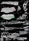
The partial stem actinopterygian coronoid. (a) Occlusal view. Rectangle, close‐up area shown in Figures 4, 5, 6; ovals, two pairs of predecessor and successor teeth shown in Figure 7. (b) Antero‐lingual view. Red planes, the sectioning planes of the virtual thin sections in (e, f). (c) Postero‐labial view. Green planes, the sectioning planes of the virtual thin sections in (g, h). Note that the labial surface of the dental shelf and keel is pitted by the lacunae of osteoblasts that have not been incorporated into the mineralized bone. (d) Anterior view. Blue plane, the sectioning plane of the virtual thin sections in (i). (e, f) Transverse sections. (g, h) Horizontal sections. (i) Longitudinal section. Round‐head pin, presumed contact ridge with prearticular; flat‐head pin, presumed contact surface with anterior coronoid; diamond‐head pin, presumed supporting ridge holding the dental shelf of dentary. U‐turn arrow, bone resorption. Double‐head arrow, bone redeposition. cf., collagen fiber; cf.c, collagen fiber in cross‐section; di, dentine increment; dr1, dentine remnant of the first‐generation primary tooth; dr2, dentine remnant of the second‐generation primary tooth; drn, dentine remnant of the replacement tooth; ds, dental shelf; dt, dentine tubule; en, enamel; lag, line of arrested growth; k, keel; ob, osteoblast imprints; oc, osteocyte lacuna; occ, osteocyte canaliculus; rl, reversal line; Sf, Sharpey's fiber; Sf.c, Sharpey's fiber in cross‐section; TB, tooth base; TC, tooth crown. (a, b) Anterior to the left. (c, g–i) Anterior to the right. (a–d) To the same scale. (e, f) To the same scale. (g, h) To the same scale. Insets from the same virtual thin section are to the same scale.
FIGURE 2
FIGURE 2
Organization of first‐ and second‐generation primary teeth, the teeth that are attached directly to the bone surface. (a) Ventral view of the basal canals. The coronoid is rendered semi‐transparent. Mirrored horizontally, anterior to the left, as (b, c). (b) Occlusal view. Note the tooth base shape and the overlap between tooth rows. Several teeth in the most lingual row have been eroded by bone remodeling. (c) Schematic diagram of tooth row organization based on (b). Dashed line, resorbed or broken section of the tooth row. (d) Labial view. Note the anterior climbing of teeth in each row and labial climbing of tooth rows: the more anterior the tooth in a tooth row, the higher it is located; the more labial the tooth row, the higher it is located. The earliest teeth at the postero‐lingual portion of the coronoid have the tooth bases, as well as the tooth crowns, resorbed. (e) Postero‐ventral view. (f) Same view as (e), with the coronoid rendered solid. U‐turn arrows indicate the lingual resorption and ventral resorption at the earliest tooth positions. (a–e) to the same scale.
FIGURE 3
FIGURE 3
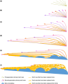
Schematic of the patterning logic of the stem actinopterygian coronoid, save view as Figure 2b. (a) Antero‐labial tooth addition of the first‐generation radial tooth rows. (b) Antero‐labial tooth addition of the second‐generation radial tooth rows. (c) Radial‐linear transition of the second‐generation tooth rows, with the lingual ones entering into the in situ replacement cycles. (d) All second‐generation tooth rows extend anteriorly into linear rows. All the second‐generation teeth are gradually shed semi‐basally and replaced labially. (e) After multiple replacement cycles, the tooth positions have drifted labially overlapping the original site of the tooth positions in the next row. Extensive lingual bone remodeling terminates the in situ tooth replacement at the lingual tooth positions, pushing the dental competent zone labially. (f) Cross‐position tooth replacement occurs at the labial positions due to the retention of the tooth bases of the second‐generation teeth and the labial shift of the dental competent zone. The developmental dynamic of the coronoid dentition is the result of the interaction among three events that set off sequentially and then take place in parallel: Tooth addition of the second‐generation teeth as the bone grows, represented by the pinkish to purplish lines with arrowheads indicating the direction of tooth row extension; tooth replacement, represented by golden lines that eventually join up into an area; extensive bone resorption and redeposition, represented by blue semi‐circles. Note that the anterior increase of the linguo‐labial compression of the teeth is correlated with the decrease of the inter‐line space.
FIGURE 4
FIGURE 4
The labial addition of the second‐generation tooth rows in line with the appositional growth of bone. (a) The fourth tooth row. Anterior teeth invariably overlap the edge of posterior teeth. (c) The addition of the fifth tooth row. Tooth 5/6 is added labially to the gap between the Teeth 4/5 and 4/6, overlapping their edges. Tooth 5/7 is added to the gap between Teeth 4/6 and 4/7, but considerably overlaps Tooth 4/6. The overlap between Teeth 5/8 and 4/7 even increases. Resorption of Teeth 4/6 and 4/7 occurred before the addition of Teeth 5/7 and 5/8, and the pulp cavities of Teeth 4/6 and 4/7 diverge [arrowhead in (a)] with one branch leading to the pulp cavities of Teeth 5/7 and 5/8, respectively. (e) The addition of the sixth tooth row. Tooth 6/5 is added labially to Tooth 4/5, and tooth 6/6 labial to Tooth 4/6, overlapping the edge of Tooth 4/6. (b, d, f) The same virtual thin section as Figure 1f, with the sectioning plane indicated in (a). The bone layers associated with each tooth row shown in (a, c, e) are highlighted. All to the same scale.
FIGURE 5
FIGURE 5
The splitting and merging of tooth positions. (a, b) Teeth 3/6 and 3/7 are subject to extensive resorption (quad arrow) or site‐specific resorption (bent arrow), and then split into two tooth positions (diverging arrow), with one connecting with the pulp cavities of the second‐generation primary teeth in the adjacent labial tooth row (arrow). (c) The four lingual tooth positions resulted from the split, as well as some other labial tooth positions (asterisk), each undergoes in situ replacement. (d–g) The pulp cavity of a post‐functional position can split and support different new tooth positions (arrowhead). (d, e) Pairs of the tooth positions undergo united resorption (double‐head arrow) to create a merged tooth position (asterisk). The pulp cavities of the teeth at the merged positions, apart from connecting to the pulp cavities of the pair tooth positions from below, also join the pulp cavities of adjacent lingual positions (arrow). (f, g) Pulp cavities of adjacent positions (arrowhead) can also merge into a new tooth position (asterisk) even though they are not resorbed in pairs. (f) Tooth 7/7 is added to the gap between Teeth 6/5 and 6/6, with the pulp cavity connecting to that of Tooth 5/6. (g–i) Resorption does not affect functional teeth (circular arrow), but worn teeth (h, dashed line) or teeth that have been eroded by bone remodeling (i, dashed line). (i) The dentine remnants of two successive replacement teeth are stacked (chevron), but the third one only has the labial side of the tooth base retained (dashed line) due to the lingual bone resorption. All to the same scale.
FIGURE 6
FIGURE 6
The most labial and the most lingual teeth. (a) The pulp cavities of the youngest teeth at the most labial rows all have an antero‐labially pointed end (asterisk) and a connection to the pulp cavity of the tooth lingual to them (arrow). (b) Tooth 6/7, the youngest tooth of the sixth row, added labial to Tooth 4/7, considerably overlaps the replacement teeth of adjacent tooth positions and sits on a resorption surface. The upcoming Tooth 7/8, indicated by the vascular bit incorporated in the most labial new bone layer between Tooth 6/7 and the replacement tooth of Tooth 6/6, labial to Tooth 5/7, is expected to overgrow the adjacent teeth too. (c) The same virtual thin section as Figure 4b,d,f, with the sectioning plane indicated in (b). The bone layers associated with the most labial replacement tooth are highlighted. (d, e) Tooth 2/1 is replaced in situ consecutively and the replacement teeth drift posteriorly, while the anterior position split from Tooth 3/6 drifts anteriorly (chevron). Their drifted replacement teeth merge into a large tooth position (arrowhead). (f) Virtual thin section with structures shown in (e) highlighted. Sectioning plane indicated in (e). (g, h) The stack of resorption surfaces (chevron) of the merged large position (asterisk). (i) Surface view of the area. The toothless surface of the lingual region of the coronoid is the result of bone remolding around the most lingual tooth positions [u‐turn arrow in (f)]. Two large openings (green) in the toothless region suggest the vascular connection to the epithelium is maintained in the pulp cavities of the plugged sockets of the tooth positions 3/6 and 3/7. All to the same scale.
FIGURE 7
FIGURE 7
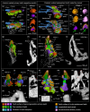
The labial replacement and hypermineralized capping tissues of the two unshed teeth. (a–k′) The unshed primary tooth PT4/10 and the neighboring teeth at the anterior portion of the specimen. (l–x′′) The unshed replacement tooth RT5/3‐1 and the neighboring teeth at the posterior portion of the specimen. (a‐b, l–m) Occlusal view, anterior to the left. (a, l) show the basal remnants of the three second‐generation primary teeth and (b, m) show their replacement teeth and resorption surfaces. (c–f) The tooth tip of PT4/10. (n–s) The tooth tip of RT5/3‐1. (c‐d, n‐o) Apical view. (e‐f, p–s) Side view. (c, e, n, p) Tooth surface. (d) The first dentine layer. Its outer surface represents the acrodin‐dentine junction and its inner surface represents the first dentine increment. Note the fine pores on the outer surface as penetrated by fine (branched) dentine tubules. (f) Clipping of the model, showing that the acrodin‐dentine junction is concentric with the dentine increment, but not with the tooth surface. (o, q) The inner surface of enamel, representing the enamel‐dentine junction. Note the enamel ridges run consistently with those on the tooth surface. (r) The third dentine layer and the apical remnant of the pulp cavity. Note the larger pores on the dentine surface as penetrated by thick (grouped) dentine tubules. (s) Clipping of the model, showing that the outer surface of dentine, represented by the enamel‐dentine junction, is not concentric with the dentine increments that separate dentine layers. (g‐h, t‐u) Labial to the left. (g, t) Anterior view of (b, m), but resorption surfaces and basal canals are not shown. Layers of bone are indicated by osteocytes. Osteocyte canaliculi are not shown. (h, u) Virtual thin sections through (g, t). (i‐j, v‐w) The labial resorption of the unshed teeth, indicated by the resorption surfaces in sapphire blue. (j, w) only shows the successive teeth and pulp column at the tooth position 4/10 and 5/3; (i) also shows the primary tooth labial to PT4/10 (PT5/10) and its resorption surface (rs5/10), demonstrating that RT4/10‐1 is not the replacement tooth of PT5/10; (v) also shows the primary tooth labial to tooth RT5/3‐1 (PT7/4) and its resorption surface (rs7/4), demonstrating that RT5/3‐2 is not the replacement tooth of PT7/4. Except in (c–f, n–s), the tooth surface of PT4/10, RT4/10‐1, RT5/3‐1 and RT5/3‐2 are rendered transparent to show the acrodin/enamel‐dentine junction and pulp cavity. (k, x) Virtual thin sections through (j, w). (k′, x′, x′′) Magnifications of the red rectangles in (k, x). ac, acrodin; adj, acrodin‐enamel junction; bl, burial line, below which the tooth is embedded in other hard tissues; ceb, collar enamel border; cg, crystal grouping; de, dentine; dt, dentine tubule; dts, dentine tubule space; ec, enamel crest; edj, enameloid‐dentine junction; en, enamel; mt, microtubercle; pc, pulp cavity; rs, resorption surface; wf, wear facet. (c–f, n–s) to the same scale, scale bar = 25 μm; (k′, x′, x′′) to the same scale, scale bar = 10 μm; the rest to the same scale, scale bar = 100 μm.

References

    1. Ahlberg, P.E. & Clack, J. (1998) Lower jaws, lower tetrapods – a review based on the Devonian genus Acanthostega . Transactions of the Royal Society of Edinburgh: Earth Sciences, 89, 11–46.
    1. Amini, S. , Razi, H. , Seidel, R. , Werner, D. , White, W.T. , Weaver, J.C. et al. (2020) Shape‐preserving erosion controlled by the graded microarchitecture of shark tooth enameloid. Nature Communications, 11(1), 5971. Available from: 10.1038/s41467-020-19739-0 - DOI - PMC - PubMed
    1. Andreev, P.S. , Coates, M.I. , Karatajūtė‐Talimaa, V. , Shelton, R.M. , Cooper, P.R. , Wang, N.Z. et al. (2016) The systematics of the Mongolepidida (Chondrichthyes) and the Ordovician origins of the clade. PeerJ, 4(6), 1–38. Available from: 10.7717/peerj.1850 - DOI - PMC - PubMed
    1. Andreev, P.S. , Sansom, I.J. , Li, Q. , Zhao, W. , Wang, J. , Wang, C.C. et al. (2022a) Spiny chondrichthyan from the lower Silurian of South China. Nature, 609(7929), 969–974. Available from: 10.1038/s41586-022-05233-8 - DOI - PubMed
    1. Andreev, P.S. , Sansom, I.J. , Li, Q. , Zhao, W. , Wang, J. , Wang, C.C. et al. (2022b) The oldest gnathostome teeth. Nature, 609(7929), 964–968. Available from: 10.1038/s41586-022-05166-2 - DOI - PubMed