Review
. 2025;221(2):30.
doi: 10.1007/s11214-025-01154-w. Epub 2025 Mar 13.

The Analyzer for Cusp Ions (ACI) on the TRACERS Mission

Affiliations
Review

The Analyzer for Cusp Ions (ACI) on the TRACERS Mission

Stephen A Fuselier et al. Space Sci Rev. 2025.

Abstract

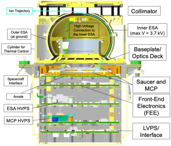
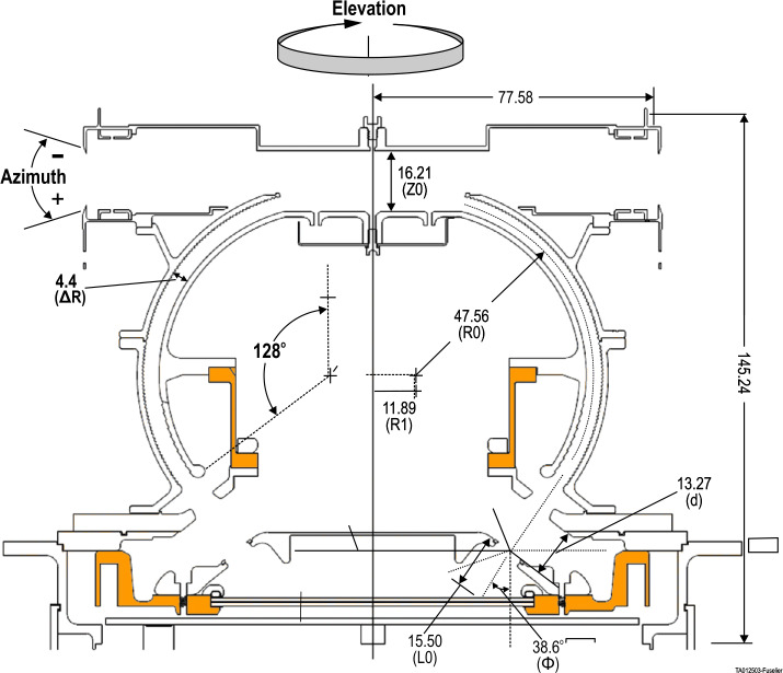
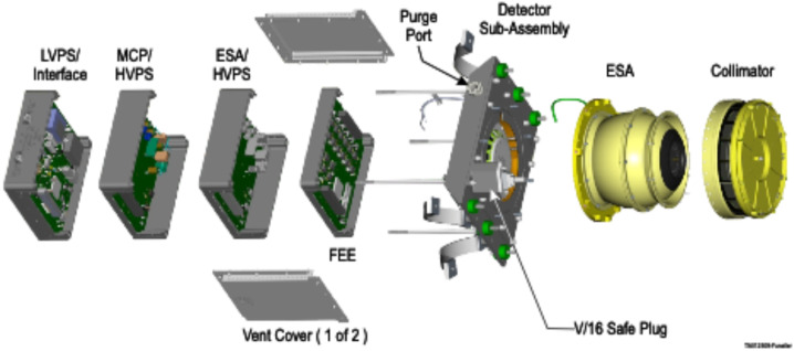
The Analyzers for Cusp Ions (ACIs) on the TRACERS mission measure ion velocity distribution functions in the magnetospheric cusp from two closely spaced spacecraft in low Earth orbit. The precipitating and upflowing ion measurements contribute to the overarching goal of the TRACERS mission and are key to all three science objectives of the mission. ACI is a toroidal top-hat electrostatic analyzer on a spinning platform that provides full angular coverage with instantaneous 22.5° × ∼6° angular resolution for a single energy step. ACI has an ion energy range from ∼8 eV/e to 20,000 eV/e covered in 47 logarithmic-spaced energy steps with fractional energy resolution of ∼10%. It provides reasonably high cadence (312 ms) measurements of the ion energy-pitch angle distribution with good sensitivity and energy resolution, enabling detection of cusp boundaries and characterization of cusp ion steps.

Keywords: Electrostatic analyzer; Ions; Magnetic reconnection; Magnetosphere; TRACERS mission.


Conflict of interest statement

Competing InterestsThere are no conflicts of interest in this submission.

Figures

Fig. 1
Fig. 1
(top) Schematic illustrating how magnetic reconnection at the Earth’s magnetopause produces a time-of-flight effect where faster ions precipitate at lower latitudes in the cusp. ACI’s primary requirement is to measure this time-of-flight effect. (bottom) Ion energy-time spectrogram from one of the TRICE-2 ion instruments showing this time-of-flight energy-latitude dispersion in the cusp. The white line traces the low-energy cutoff of this dispersion. The dispersion is not smooth. Instead, it occurs over a series of “steps”. Measuring these cusp ion steps from the two TRACERS spacecraft is a key objective of the mission
Fig. 2
Fig. 2
Cut-away view of ACI. The upper half of the analyzer is rotationally symmetric about the center line. Ions enter the collimator and are deflected into the ESA. The inner ESA has a negative voltage on it, supplied by the ESA HVPS. Ions with the correct energy (based on the ESA voltage) traverse the gap between the inner and outer ESA, exit the ESA and strike the MCP detector. The MCP and “saucer” are biased at a negative potential from the MCP HVPS. The resulting electron cloud from the bottom of the MCP stack strikes one of 16 anodes on the anode board. This signal is amplified by the FEE and it is sent to the LVPS/Interface for transmission to the MEB
Fig. 3
Fig. 3
Cut-away view of the ACI ion optics. Azimuth angles are measured from the incident ion direction so that positive angles are for ions with “upward” velocity vectors. Elevation angles are measured clockwise about the center axis. Parts in orange are insulators that stand off the ESA and MCP high voltages and the rest of the parts are conductors. The top-hat ESA is slightly toroidal and the ions are deflected through an angle of 128°. Because the bend angle is >90°, the focal point of the ion beam is energy-dependent. The ions strike the MCP at a somewhat oblique angle, Φ = 38.6°. This oblique angle of incidence results in an MCP gain that is elevation angle dependent
Fig. 4
Fig. 4
Exploded view of ACI. The collimator is attached to the ESA and this unit is attached to the detector sub-assembly. The detector sub-assembly is the interface to the side panel of the spacecraft and the analyzer is thermally isolated by 6 washers on the top of the detector sub-assembly. The 4 electronics boards in their frames are stacked and interconnected by electrical connectors on each board. The stack is held together by the 4 skewers on the detector sub assembly
Fig. 5
Fig. 5
Mechanical ACI hardware. (top left) The inside of the upper outer ESA showing serration and blackening for UV background rejection. (top right) the fully assembled collimator and ESA, (bottom left) the outer ESA upper and lower pieces, (bottom right) the underside of the assembled ESA showing the 16 windows of the baseplate and the high-voltage electrical connection to the inner ESA
Fig. 6
Fig. 6
A detailed view of (left) the ACI MCPs in their holder and (right) the anode board under the MCP stack. The MCPs and the anode board are housed in the detector sub-assembly
Fig. 7
Fig. 7
The four ACI electronics boards from Fig. 4 in detail. (top left) the FEE board, (top right) the LVPS/Interface board, (bottom left) the MCP HVPS board, and (bottom right) the ESA HVPS board
Fig. 8
Fig. 8
Normalized count rate versus MCP voltage from the ACI1 (red curve) and ACI2 (black curve) gain tests. The setpoint for operating the ACI1 and ACI2 MCPs in saturation −1650 V and −1550 V, respectively. Beyond these voltages, the MCPs operate in saturation and the normalized count rate will either remain constant or decrease as shown
Fig. 9
Fig. 9
Average counts versus discriminator settings for all 16 anodes from the ACI2 final calibration. The Dec units are a percentage of the Pulse Width Modulation with the full range of 3.3 V divided into 2048-Dec bit levels. As the discriminator setting, or Threshold Level (TL) is increased, the noise is rejected and eventually the real signal decreases. The ACI2 discriminator setting is a balance between rejecting noise and maximizing real signal for all anodes
Fig. 10
Fig. 10
Detected versus incident count rate for the ACI2 rate versus rate test that was conducted as part of final calibration. As the incident count rate increases, the detected count rate begins to plateau (grey squares). A system deadtime τ = 2.31 μs corrects the measured count rate (red circles). The red line is the one-to-one line showing the corrected count rate equal to the expected count rate
Fig. 11
Fig. 11
Average counts as a function of elevation angle for an elevation scan of ACI2. The signal gain is a function of elevation (anode) because the ions are not incident normal to the MCP (see Fig. 3). The variation in the gain over the 360° elevation scan is about 25%. For each individual anode, there is physical blockage by the baseplate and saucer windows and there is small spillover to adjacent anodes. The full-width-half-maximum of a scan averaged over all anodes is the elevation response Δβ listed in Table 3
Fig. 12
Fig. 12
The analyzer constant versus anode for ACI2. The analyzer constant varies between 5.4 and 5.5 for most anodes, which translates to an uncertainty in the inner and outer ESA separation, ΔR, of about 30 microns out of an average ΔR of 4.4 mm (see Fig. 3)
Fig. 13
Fig. 13
The energy-azimuth response of ACI1 for a ∼10 kV beam at anode 14 measured during final calibration. The energy scale is converted to an analyzer constant scale (in eV/v). The 1-D histogram of integrated k shows that this response is not symmetric over k or azimuth. The test shows that the analyzer field-of-view is tilted “upward” in azimuth by about 1°
Fig. 14
Fig. 14
Same as Fig. 13, but for ACI2 at anode 15
Fig. 15
Fig. 15
Geometric factor as a function of energy for ACI2. Because of the energy-dependent focusing properties of the ESA, the geometric factor has an energy dependence. The overlap of the geometric factor measured before environmental qualification and after qualification indicates that the analyzer characteristics remained nearly constant pre- and post-environmental qualification
Fig. 16
Fig. 16
Diagram of ACI as mounted on the TRACERS spacecraft, showing the anodes and select anode look directions relative to the spacecraft spin axis and direction of the magnetic field in the northern cusp. During the pass through the northern cusp, precipitating ions would be primarily measured by anodes 3-5 and upflowing ions would be measured by anodes 11-13. Every half-spin, anodes 8 and then 0 are aligned with the motion of the spacecraft along the orbit. In the northern cusp, every half-spin, anodes 1 and 7 are approximately aligned with the direction to the Sun
Fig. 17
Fig. 17
TRACERS ACI2 installed on the motion system of the EPIC calibration facility. The rear of the Faraday cup used for beam verification is to the left of ACI2. At the right is the hexapod base, where the ACI adapter bracket is attached

References

    1. da Silva D, Chen LJ, Fuselier S, Wang S, Elkington S, Dorelli J, et al. (2022) Automatic identification and new observations of ion energy dispersion events in the cusp ionosphere. J Geophys Res Space Phys 127:e2021JA029637. 10.1029/2021JA029637
    1. Halekas JS, Hansen C, Ruhunusiri S, Sheets D, et al (2025) The TRACERS analyzer for cusp electrons. Space Sci Rev 221:21. 10.1007/s11214-025-01147-9 - PMC - PubMed
    1. Miles DM, Fuselier S, Goodrich K, Kletzing C (2025) Mission overview of the TRACERS Small Explorers mission. Space Sci Rev 221
    1. Onsager TG, Chang S-W, Perez JD, Austin JB, Jano LX (1995) Low-altitude observations and modeling of quasi-steady magnetopause reconnection. J Geophys Res 100:11831–11843
    1. Petrinec SM, Kletzing CA, Miles D, Fuselier SA, Christopher IW, et al (2025) The Tandem Reconnection and Cusp Electrodynamics Reconnaissance Satellites (TRACERS) mission design. Space Sci Rev 221

LinkOut - more resources