. 2025 Mar 19;22(2):026023.
doi: 10.1088/1741-2552/adba8b.

An active electronic, high-density epidural paddle array for chronic spinal cord neuromodulation

Affiliations

An active electronic, high-density epidural paddle array for chronic spinal cord neuromodulation

Samuel R Parker et al. J Neural Eng. .

Abstract

Objective. Epidural electrical stimulation (EES) has shown promise as both a clinical therapy and research tool for studying nervous system function. However, available clinical EES paddles are limited to using a small number of contacts due to the burden of wires necessary to connect each contact to the therapeutic delivery device, limiting the treatment area or density of epidural electrode arrays. We aimed to eliminate this burden using advanced on-paddle electronics.Approach. We developed a smart EES paddle with a 60-electrode programmable array, addressable using an active electronic multiplexer embedded within the electrode paddle body. The electronics are sealed in novel, ultra-low profile hermetic packaging. We conducted extensive reliability testing on the novel array, including a battery of ISO 10993-1 biocompatibility tests and determination of the hermetic package leak rate. We then evaluated the EES devicein vivo, placed on the epidural surface of the ovine lumbosacral spinal cord for 15 months.Main results.The active paddle array performed nominally when implanted in sheep for over 15 months and no device-related malfunctions were observed. The onboard multiplexer enabled bespoke electrode arrangements across, and within, experimental sessions. We identified stereotyped responses to stimulation in lower extremity musculature, and examined local field potential responses to EES using high-density recording bipoles. Finally, spatial electrode encoding enabled machine learning models to accurately perform EES parameter inference for unseen stimulation electrodes, reducing the need for extensive training data in future deep models.Significance. We report the development and chronic large animalin vivoevaluation of a high-density EES paddle array containing active electronics. Our results provide a foundation for more advanced computation and processing to be integrated directly into devices implanted at the neural interface, opening new avenues for the study of nervous system function and new therapies to treat neural injury and dysfunction.

Keywords: epidural electrical stimulation; hermetic electronics; high density array; implanted device; neuromodulation; spinal electrophysiology.


Conflict of interest statement

SRP, JSC, RD, and DAB have patents pending regarding the recording of spinal electrophysiological signals during spinal cord stimulation (PCT-US2022-034450: ‘A novel method to modulate nervous system activation based on one or more spinal field potentials’). BM, KA, GC have patents and pending patents related to high-resolution spinal cord stimulator devices (US-11 116 964-B2: ‘Multi-electrode array with unitary body’, 11 027 122: ‘Spinal cord stimulation method to treat lateral neural tissues’, US-11 395 924-B2: ‘Implantable devices with welded multi-contact electrodes and continuous conductive elements’). Micro-Leads Medical is a commercial company developing precision neuromodulation therapeutic devices and BM, KA, GC, and YI are shareholders or have stock options in Micro-Leads.

Figures

Figure 1.
Figure 1.
The HD64: active electronics hermetically sealed into an epidural electrode paddle array. (a) A functional block diagram of the application specific circuit (ASIC) embedded on the spinal paddle. (b) A photograph of the ASIC die (redistribution layer and solder ball placement shown). (c) An exploded 3D render of the hermetic package. From top to bottom, we show the titanium 6–4 top case, the balled ASIC, a novel alumina feedthrough array, and the feedthrough pins. (d), (e) Photographs of the assembled hermetic feedthrough package. (f) The hermetic package is precision aligned within <10 μm onto the electrode before conductors are thermally micro-bonded followed by silicone injection molding. (g) A histogram of the hermeticity leak rates measured from 171 hermetic packages. The MIL-STD-883K helium leak failure threshold is overlaid as the red dashed line. (h) Left to right: a photograph of the dorsal side of the molded HD64 paddle array, a photograph of the 2 12-contact lead tail connectors, and a photograph of the ventral side of the array, showing the 60-contact grid. (i) Side- and front-on photographs comparing the lower-volume profile of the HD64 compared to a Boston Scientific CoverEdge32 surgical paddle.
Figure 2.
Figure 2.
An overview of the in vivo evaluation of the HD64. (a) A schematic representation of the connections and devices used to evaluate the HD64. The host PC controls the collection of spinal electrophysiology, application of transcutaneous electrical nerve stimulation (TENS) and epidural electrical stimulation (EES), and the configuration of the onboard ASIC through the multiplexer controller. In S1 and S2, electromyographic (EMG) signals are collected from implanted, wireless intramuscular EMG telemetry devices or wireless surface EMG devices, respectively. AFE is the analog front end, BF is the biceps femoris, Gas is the gastrocnemius, and EDL is the extensor digitorum longus. (b) A radiograph of sheep 1, showing a single HD64 implanted. (c) A radiograph of sheep 2, showing two HD64s implanted. (d) The violin plots demonstrate that contact impedance remained stable over time, up to 274 d post-implantation.
Figure 3.
Figure 3.
Clustering analysis of motor outputs evoked by monopolar stimulation. (a) A graphical overview of the electromyography (EMG) preprocessing. A representative EMG trace (black) is rectified (blue trace), then the rectified area under the curve is calculated (blue shaded region). A sample recruitment curve is shown for six muscles. The points are the mean, and the bars show the standard deviation. A blue dashed line indicates the 33% of maximum activation threshold used for panel b. (b) The minimum required epidural electrical stimulation (EES) amplitude required to recruit each of the six instrumented muscles to 33% of their maximum activation. Electrodes marked ‘N.R.’ could not recruit the muscle to 33% of its maximum activation at the amplitude range tested. (c) A 2D projection of the embedded recruitment data. Each point is a stimulation event, and the points are colored by which cluster the stimulating electrode resides in. (d) A diagram of the HD64, with the electrode contacts colored by which cluster the electrode resides in. A scale drawing of the Medtronic 5-6-5 is overlaid to highlight which cluster(s) each of the 5-6-5’s electrodes contact. (e) Representative radar plots (EES frequency = 50 Hz) show the mean responses for each stimulation contact cluster. The clusters exhibit diverse recruitment patterns and relationships with amplitude.
Figure 4.
Figure 4.
Assessing spinal responses detected by monopolar, wide bipolar, and narrow bipolar recordings. (a) A graphical overview of the spinal local field potential (LFP) recording, epidural electrical stimulation (EES) and transcutaneous electrical nerve stimulation (TENS) setup. (b) A map of the HD64, showing the stimulation cathode (red) and anode (blue). The recording bipoles and their distances from stimulation are shown. (c) The mean and standard deviation of the spinal evoked compound action potential (ECAP) response recorded using various bipolar pairs along the midline of the spinal cord, for three stimulation amplitudes. The peak of the 4 mA stimulation response is shown with a black arrow. Note that peak latency increases with separation from the stimulation bipole. (d) The peak latencies of 50 single trials, plotted as a function of separation from the stimulating bipole, for each stimulation amplitude. The samples are colored by their recording bipole. A linear fit is plotted in blue, with the conduction velocity (CV) inset.
Figure 5.
Figure 5.
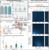
Evaluating the performance of the forward neural network model to predict sensorimotor computations. In all boxplots the horizontal bar is the median, the boxes extend from the 25th to the 75th percentile, and the blue dots represent a ‘random’ baseline performance. Statistical significance was calculated using a Kruskal–Wallis non-parametric test, with a maximum p-value of 0.05. (a) A map of the electrode contacts included in the training dataset for each model. Included electrodes are shaded blue. (b) (top) The distribution of L1 errors between the ground truth and simulated electromyography (EMG) for a held out dataset of 480 stimulation parameter combinations for the three models. (bottom) The data in (top) split by inclusion of the stimulating electrode in the training dataset. (c) An example target normalized electromyography (EMG) vector is shown at the top. The posterior densities over are shown for 3 models. Higher likelihood regions are indicated in lighter colors. (d) The in vivo evaluation procedure. The posterior densities of each model are sampled to produce proposed stimulation parameter combinations for each target. These parameters are applied in vivo, and the evoked EMG vector is calculated. The L1-error between the target EMG vector and the evoked EMG vector is then computed. (e) The distribution of mean L1 errors between the target EMG vector and the evoked EMG vector for each of the three models, and between EMG vectors evoked using identical stimuli in the training and evaluation sessions (‘ground truth’, or GT).

Update of

References

    1. Angeli C A, Boakye M, Morton R A, Vogt J, Benton K, Chen Y, Ferreira C K, Harkema S J. Recovery of over-ground walking after chronic motor complete spinal cord injury. New Engl. J. Med. 2018;379:1244–50. doi: 10.1056/NEJMoa1803588. - DOI - PubMed
    1. Badi M, et al. Intrafascicular peripheral nerve stimulation produces fine functional hand movements in primates. Sci. Trans. Med. 2021;13:eabg6463. doi: 10.1126/scitranslmed.abg6463. - DOI - PubMed
    1. Bonizzato M, et al. Autonomous optimization of neuroprosthetic stimulation parameters that drive the motor cortex and spinal cord outputs in rats and monkeys. Cell Rep. Med. 2023;4:101008. doi: 10.1016/j.xcrm.2023.101008. - DOI - PMC - PubMed
    1. Boston Scientific Surgical leads directions for use. 2020. (available at: www.bostonscientific.com/content/dam/elabeling/nm/92395562-01_B_Surgical...)
    1. Bryson N, Lombardi L, Hawthorn R, Fei J, Keesey R, Peiffer J D, Seáñez I. Enhanced selectivity of transcutaneous spinal cord stimulation by multielectrode configuration. J. Neural Eng. 2023;20:046015. doi: 10.1088/1741-2552/ace552. - DOI - PMC - PubMed

LinkOut - more resources