. 2025 Mar;639(8056):922-927.
doi: 10.1038/s41586-025-08662-3. Epub 2025 Mar 19.

Down-converted photon pairs in a high-Q silicon nitride microresonator

Affiliations

Down-converted photon pairs in a high-Q silicon nitride microresonator

Bohan Li et al. Nature. 2025 Mar.

Abstract

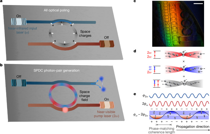
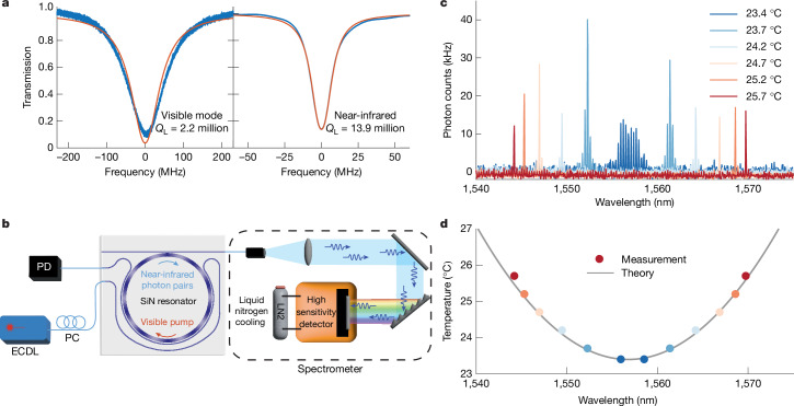
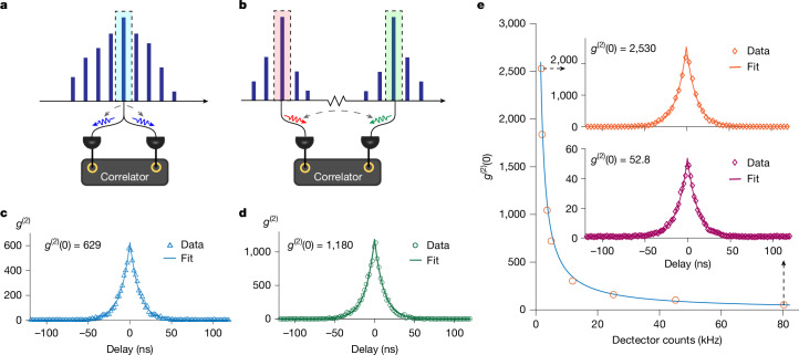
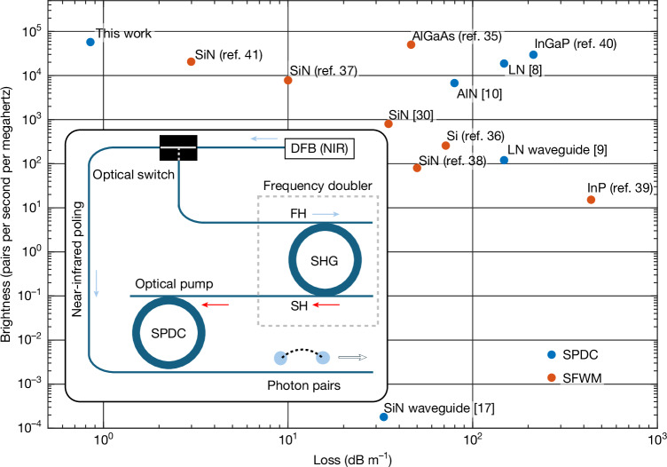
Entangled photon pairs from spontaneous parametric down-conversion (SPDC)1 are central to many quantum applications2-6. SPDC is typically performed in non-centrosymmetric systems7 with an inherent second-order nonlinearity (χ(2))8-10. We demonstrate strong narrowband SPDC with an on-chip rate of 0.8 million pairs per second in Si3N4. Si3N4 is the pre-eminent material for photonic integration and also exhibits the lowest waveguide loss (which is essential for integrated quantum circuits). However, being amorphous, silicon nitride lacks an intrinsic χ(2), which limits its role in photonic quantum devices. We enabled SPDC in Si3N4 by combining strong light-field enhancement inside a high optical Q-factor microcavity with an optically induced space-charge field. We present narrowband photon pairs with a high spectral brightness. The quantum nature of the down-converted photon pairs is verified through coincidence measurements. This light source, based on Si3N4 integrated photonics technology, unlocks new avenues for quantum systems on a chip.


Conflict of interest statement

Competing interests: The authors declare no competing interests.

Figures

Fig. 1
Fig. 1. Principle of photogalvanic-induced SPDC.
a, Depiction of the formation of a periodic space-charge grating in a Si3N4 microresonator. Input light at ω (1,560 nm) is coupled into the resonator, and an initial weak second-harmonic signal at 2ω (780 nm) is generated through symmetry breaking, for example, at the waveguide–cladding interface. The co-propagating input light and second-harmonic signal induce a periodic space-charge distribution. The resulting electric field combined with the inherent χ(3) of Si3N4 creates an effective χ(2), thereby further enhancing the second-harmonic signal. b, Depiction of SPDC in a Si3N4 microresonator. After the space-charge grating forms (a), pump light at 780 nm is coupled into the resonator and near-infrared entangled photon pairs are generated by SPDC at 1,560 nm. The lasers (both 1,560 and 780 nm) and resonators can be integrated on a semiconductor photonic chip. c, Photograph of a section of the 8-inch wafer showing the many Si3N4 resonators used in this work (highlighted region). d, The photogalvanic process relies upon two-photon transitions (780 nm) and three-photon transitions (one 780 nm photon and two 1,560 nm photons) that occur simultaneously in Si3N4. Quantum interference of these two processes breaks the symmetry and creates a field that induces drifting by the conduction electrons generated by the absorption process. e, Diagram of the charge distribution with respect to the phase of two optical signals along the propagation direction. The net space-charge accumulation is proportional to the phase difference between two optical frequencies (ϕ2ω − 2ϕω). This space-charge distribution and the resulting electric field quasi-phase-match the momentum difference for SHG. Scale bar, 5 mm.
Fig. 2
Fig. 2. Experimental results for photon-pair generation.
a, Measurements of resonator Q factors for the near-visible (left) and near-infrared (right) modes. Blue traces are measurements, and red traces are the theoretical fit. QL stands for loaded Q factor. b, Experimental set-up for SPDC spectral measurements. A 780 nm external-cavity diode laser pumps the resonator, and SPDC photons are analysed by a liquid-nitrogen-cooled high-sensitivity spectrometer. c, SPDC photon spectra measured at several chip temperatures as given in the legend. d, Measured wavelength-temperature dependence (dots) is plotted along with the theoretical calculation based on thermal frequency tuning. ECDL, external-cavity diode laser; PC, polarization controller; PD, photodetector; LN2, liquid nitrogen.
Fig. 3
Fig. 3. Second-order quantum-correlation measurement.
a,b, Illustration of the measurement set-up showing degenerate (a) and non-degenerate (b) cases. c, Measured g(2) for the degenerate SPDC case through self-correlation. d, Measured g(2) for the non-degenerate SPDC case through cross-correlation of the signal and idler photons. e, Measured g(2)(0) of non-degenerate SPDC at different pump powers. The red open circles show the g(2)(0) at different detector count rates, and the blue curve is an inverse proportional fit. Insets, g(2)(0) = 2.530 was obtained with a 17.2 kHz on-chip photon-pair generation rate, and g(2)(0) = 52.8 was obtained with a 795 kHz on-chip pair generation rate.
Fig. 4
Fig. 4. Measured SFWM and SPDC brightness and loss performance comparison.
The results achieved in this work are compared with other integrated quantum photonics platforms using two metrics, waveguide optical loss and source brightness–,,,–. The source brightness metric has been frequently used in this context. The waveguide loss metric is of critical importance for integrated quantum systems as it impacts quantum state transport across the semiconductor chip. The brightness was calculated from the maximum reported pair generation rate divided by the spectral span (from the resonator total quality factor). The waveguide loss was estimated from the resonator intrinsic quality factor, if not reported. The plot shows both SFWM (red points) and SPDC (blue points) processes. The pump powers used in the references are as follows: 1.5 mW (this work), 13.4 μW (ref. ), 0.45 mW (ref. ), 2.3 mW (ref. ), 0.43 mW (ref. ), 0.45 mW (ref. ), 25 μW (ref. ), 60 μW (ref. ), 2.0 mW (ref. ), 6.2 mW (ref. ), 22 μW (ref. ), 1.2 μW (ref. ) and 0.33 mW (ref. ). Inset, conceptual figure for an integrated photonic SPDC source featuring a single integrated near-infrared (telecom) DFB pump that is frequency-doubled (SHG) by a high-Q Si3N4 resonator to provide the near-visible pump for a high-Q Si3N4 resonator SPDC source. DFB, distributed feedback laser; FH, first harmonic; NIR, near-infrared; SH, second harmonic.
Extended Data Fig. 1
Extended Data Fig. 1. Experimental setup and characterization of second harmonic generation.
a An external cavity diode laser (ECDL) is amplified by an erbium-doped fiber amplifier (EDFA), and then coupled to the resonator chip using a lensed fiber. The chip-waveguide is designed to couple power in the near-IR (1560 nm) to the high-Q silicon nitride microresonator. The SH harmonic signal is coupled to the second waveguide. A microwave function generator (FG) enables frequency sweeping of the laser, and the frequency sweep is measured using a calibrated Mach-Zehnder interferometer (MZI). The transmitted 1560 nm signal and the generated SH signal are collected and sent into two photodetectors (PDs), separately. The detected electrical signals are sent into an oscilloscope (OSC). Also shown are PC: polarization controller, OSA: optical spectrum analyzer. b After the space-charge grating builds up, the on-chip transmitted pump power (blue) and generated SH power (red) are recorded when scanning the frequency of the pump laser across a cavity resonance.
Extended Data Fig. 2
Extended Data Fig. 2. Measurement of resonator dispersion relation and resonance temperature tuning coefficients.
a Measured frequency dispersion (blue circles) of the mode family in the near-IR band is plotted versus the relative mode number m. The solid red curve is a parabolic fit using D1/2π = 35.09 GHz and D2/2π = −863.7 kHz. In the plot, the mode frequencies are offset by the linear term in the Taylor expansion to make clear the second-order group dispersion, and ω0 is chosen so that m = 0 frequency matches to the the pump mode in the SHG process (1557.372 nm). b Measured frequency tuning of both near-IR (left axis) and visible (right axis) cavity mode frequencies as a function of temperature. The frequencies of the cavity mode resonances at 17.7 °C are chosen as a reference, separately.
Extended Data Fig. 3
Extended Data Fig. 3. Measured χ(2) intensity decay as a function of time at different visible pump powers.
The second-harmonic intensity is normalized to the initial condition after writing of the space-charge grating. The red (blue) circles refer to the on-chip pump power of 0.5 (1.5) mW and are fitted by a exponential function (solid lines). The decay lifetime is fitted to be 68 (40) s, respectively.

References

    1. Harris, S., Oshman, M. & Byer, R. Observation of tunable optical parametric fluorescence. Phys. Rev. Lett.18, 732 (1967).
    1. Kimble, H. J. The quantum internet. Nature453, 1023–1030 (2008). - PubMed
    1. Lvovsky, A. I., Sanders, B. C. & Tittel, W. Optical quantum memory. Nat. Photon. 3, 706–714 (2009).
    1. Zhang, H. et al. Preparation and storage of frequency-uncorrelated entangled photons from cavity-enhanced spontaneous parametric downconversion. Nat. Photon. 5, 628–632 (2011).
    1. Simon, C. Towards a global quantum network. Nat. Photon. 11, 678–680 (2017).