Review
. 2025 Feb 13;16(3):1025-1042.
doi: 10.1364/BOE.546971. eCollection 2025 Mar 1.

Visual simulation of intraocular lenses: technologies and applications [Invited]

Affiliations
Review

Visual simulation of intraocular lenses: technologies and applications [Invited]

Susana Marcos et al. Biomed Opt Express. .

Abstract

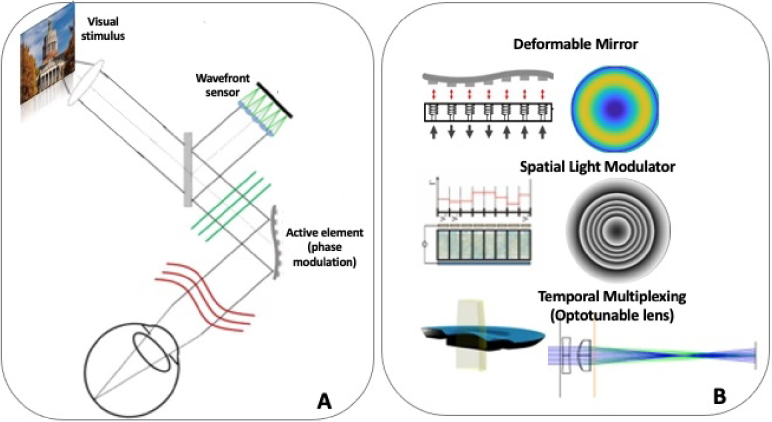
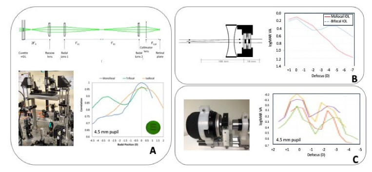
Cataract surgery requires selecting an intraocular lens (IOL), whose design affects visual outcomes. Traditional IOL evaluation relies on optical models and bench testing, but these methods fall short in simulating perceptual factors crucial to patient experience. Visual simulators, based on different principles including adaptive optics, temporal multiplexing or physical projection of the IOLs, now allow patients and clinicians to preview and compare different IOL designs preoperatively. By simulating real-world interactions of the eye's optics and the visual system with IOLs, these simulators enhance the patient decision-making process, enable personalized cataract surgery, and can aid in regulatory assessments of IOLs by incorporating pre-operative patient-reported visual outcomes. Visual simulators incorporate deformable mirrors, spatial light modulators and optotunable lenses as dynamic elements to simulate monofocal, multifocal and extended depth-of-focus IOLs, including newer designs aimed at improving contrast sensitivity, expanding depth of focus, and minimizing visual disturbances. With ongoing advancements, these simulators hold potential for transforming IOL design, regulatory processes, and patient care by providing realistic and patient-centered visual assessments, ultimately leading to more successful, individualized surgical outcomes.


Conflict of interest statement

SM discloses laboratory funding in areas related to IOLs and simulations from Alcon Research Labs (IO), BVI-PhysIOL (IO), Bausch and Lomb (UR), ClerioVision (UR); Coopervision (UR), Essilor International (IO), Johnson and Johnson (IO), Staar Surgical (IO), Meta Reality Labs (UR), Hoya (IO) for research with the described instruments. SM is a co-founder, shareholder and board member of 2EyesVision SL, a spin-off company of CSIC, which licenses related Vision Simulator technologies and is a co-inventor of patents P201730854, US9693679 and US10213358 licensed to 2EyesVision; SM is co-inventor of patent US10226327 and P201930791 (BVI/PhysIOL) and US2018042474 (Essilor) that used the described AO technology in their development. PA is a co-founder of Voptica SL, a start-up of the University of Murcia and co-inventor of patents US20120154742 and US20120038884 licensed to Voptica. LL discloses support from Johnson and Johnson; GY discloses support from Johnson and Johnson, Alcon..

Figures

Fig. 1.
Fig. 1.
A. IOL AO Visual Simulator (AOVS) general concept. IOLs are simulated on a pupil conjugate plane via an active element that reproduces the phase changes introduced by the IOL. A Hartmann-Shack (optional) allows measurement of the eye’s aberrations and (if needed) closed-loop correction. Visual stimuli are seen through the simulated correction. B. Different active elements found in AOVS: Electromagnetic Deformable mirrors (top), Spatial Light Modulator (middle) and optotunable lens (bottom), separately or simultaneously in the same system.
Fig. 2.
Fig. 2.
A. Two-channel see-through Simultaneous Vision Simulator of Bifocal IOLs. A transmissive SLM allows mapping IOLs with different zonal distribution of near and far. Badal optometers in the two channels allow variable distance correction and near add. Illustration taken from Dorronsoro et al. [33]. B. Portable see-through simulators working under the principle of temporal multiplexing with optotunable lenses. Upper and bottom left: diagram and photograph representing the system in a monocular configuration. From Dorronsoro et al. [28]. Bottom right: binocular head-mounted system where each eye can be simulated with a different lens (SimVis Gekko, courtesy of 2EyesVision).
Fig. 3.
Fig. 3.
A. Upper panel: Rassow telescope to project an IOL inserted in a cuvette onto the eye’s pupil. Lower left panel: IOL projector module (CSIC Rassow Telescope) incorporated in an Adaptive Optics Visual Simulator (IO); Lower right panel: On bench through-focus optical performance of three physical IOLs projected on the pupil plane of an artificial eye in the system. The optical quality metric is the correlation of the image of an E optotype captured in the CCD camera acting as the retina, through the system with no lens, and through a monofocal IOL (blue), trifocal IOL (green), isofocal IOL (orange) inserted in the cuvette. Illustrations are from Benedi-Garcia et al. [38]. B. Right panel: IOL simulator consisting of a trial lens tube, concave lens, and wet cell where the IOL is inserted. The system is designed to be mounted in a trial frame. Left panel: Through-focus visual performance (logMAR VA) with monofocal (red) and bifocal (blue) Tecnics IOLs. Figure adapted from Na et al [36]. C. Right panel. Photography of KTH IOL telescope. Left panel. Through-focus visual performance (logMAR VA) of the same multifocal IOL on four different cyclopeged subjects. From Lundström et al. [40]
Fig. 4.
Fig. 4.
From IOL design to IOL mapping in visual simulators. A Estimation of the IOL pupilarly phase pattern by subtraction of the wave aberration in an eye with an aberration- free lens and that of an eye with the phase under test. The phase map representing the IOL can be mapped on the deformable mirror (DM) or as a wrapped phase in a Spatial Light Modulator (SKM). The example corresponds to an Isofocal IOL. The lens profile is from Fernandez et al. [74]. The IOL photograph is from PhysIOL/BVI. Graphics are from Lago et al. [39]. B. Estimation of the time coefficients in a temporal multiplexing paradigm with a tunable lens (TL) operating at high frequency. The through-focus (TF) performance of the lens in terms of Visual Strehl or MTF is calculated from the IOL geometrical design or on bench testing, The temporal profile of the lens (time coefficients) is calculated to tailor the lens TF performance. Dynamic effects in the TL are compensated. The example is for a FineVision IOL by BVI-PhysIOL (depicted as picture and as multifocal echelette profile). Left and Middle graphs are from Akondi et al. [29] and right is from Dorronsoro et al. [46]. The TL picture is from Optotune.
Fig. 5.
Fig. 5.
Testing of novel IOL designs in Visual Simulators. A Bifocal segmented lenses in a two-channel simultaneous vision simulator. Left: Best (green dots) and Worst (red dots) judged patterns by individual subjects (and on average) at Far (F), Intermediate (I) and Near (N). 2-zone angular patterns tend to be preferred by most subjects, although their performance is very orientation-dependent. Hybrid patterns tend to be the most rejected. Results are selected from Dorronsoro et al. [28]. Right: Visual quality (scores) for one subject with a 2-Zone angular IOL design at different orientations (270 deg is the optimal orientation at Far for this subject). B. Visual ranking at far (scores range:0-5) of bifocal, trifocal and tetrafocal segmented IOL designs, simulated in an AOVS with SLM. Results are average across 5 subjects. For the same number of zones, angular (Ang) outperform radial (Rad) distributions. Quality degrades with increasing number of zones. Data from Vinas et al. [16]. C. Contrast Sensitivity in one subject (4.8 mm pupil) measured in white light, for a commercial aspheric IOL which corrects for corneal spherical aberration of the average population (red circles) and one correcting the individual spherical aberration (blue squares). Adapted from Piers et al. [41]. D. Periodic Refractive Extended Depth of Focus (PREDoF) IOL design for a 6 mm pupil (right inset). Through-focus logMAR visual acuity tested in a AOVS, with three different profiles mapped on an SLM: PREDoF IOL (blue), a typical monofocal IOL (gray) and diffractive trifocal IOL (orange). Adapted from Lyu et al. [58]. E. Visual benefit at far in terms of high contrast logMAR Visual Acuity (left) and visual preference (right) when an annular phase piston is introduced in the periphery of bifocal (blue, 0.25λ piston) or trifocal (green, 0.28λ piston) diffractive IOLs. BF stands for Bifocal, BFP Bifocal with piston, TF Trifocal, TFP Trifocal with piston. Results are selected from Goswami et al. [57]. Designs provided by ClerioVision Inc.
Fig. 6.
Fig. 6.
Pre-operative simulation of post-operative vision with real IOLs A. Post-operative visual acuity predicted by through-focus retinal image quality of the IOLs (monofocal, Mplus and Finevision) quantified with an optical bench testing system. The plot is adapted from Plaza-Puche et al. [60]). B . Through-focus logMAR Visual Acuity through a simulated diffractive trifocal IOL (custom) in patients, with the natural crystalline lens, or the high order aberrations of the crystalline lens neutralized with Adaptive Optics. Data are adapted from Villegas et al. [63] C. SimVis simulation of trifocal diffractive IOL (FineVision by BVI-PhysIOL) pre-operatively in comparison with post-operative data in the same patients post-implantation of the IOL. Data are from Vinas et al. [61]. D. SimVis simulation of trifocal diffractive (Panoptix by Alcon) (blue lines, left) and of EDOF refractive IOL (Vivity by Acon) (purple lines, right) on presbyopic patients (n = 15) in comparison with post-operative data with these IOLs from the literature. Data are from Zaytoun et al. 2019 [62].
Fig. 7.
Fig. 7.
Binocular Visual simulation of IOLs. A Left. Perceived visual score at far (horizontal axis) and at near (vertical axis) for different combinations of bilateral designs (average across 10 subjects; size of the bubble represents weight of the effect) simulated with a binocular visual simulator. Score ranges from 0 -worse- to 5 -best. F stands for monofocal IOL focused at far; I stands for monofocal IOL focused at Intermediate; N stands for monofocal IOL focused at near; BF stands for bifocal IOL; TF stands for trifocal IOL; X + Y indicates bilateral correction, where X indicates dominant eye and Y indicates non-dominant eye; X = Y indicates equal corrections in both eyes and X≠Y monovision corrections, traditional monovision if X and Y are monofocal IOLs and modified monovision if X and Y are monofocal and BF or TF, respectively, or viceversa. Highest scores of binocular visual quality are found for F + N; F in the dominant eye produces higher scores than N, BF or TF in the dominant eye. Data are compiled from Radhakrishnan et al. [31]. Right: Multifocal Acceptance Score polygons for four different combinations of IOLs tested in a presbyopic subject. Scores are for natural images at far, near, and day and night conditions, as well as stereovisual acuity. Values closer to the circle indicate highest quality. Monofocal IOLs (F + F) perform best at far, but low at near, while bifocal IOLs (BF + BF) reduce quality at far at the expense of improving at near. Standard monovision (F + N) produces high quality at far and near, but reduce stereovision. Modified monovision still produced improvement at near without compromising stereo vision in this subject. Result from Barcala et al. [65]. B. Through-focus visual acuity (left) and stereoacuity (right) for traditional monovision with +1.5D near add in the non-dominant eye, and modified monovision with a combination of primary and secondary spherical aberrations (+0.1 μm and -0.4 μ m, respectively) for a 4 mm pupil. The binocular AOVS was used for these measurements. Data are adapted from Zheleznyak et al. [42]. C. Stereo-acuity with different simulated IOL binocular combinations: natural eye (no IOL), monovision (plano dominant eye and +0.75 D in non-dominant eye), small aperture or small aperture combined with monovision. Figure taken from Fernandez et al. [73]

References

    1. Marcos S., Artal P., Atchison D. A., et al. , “Adaptive optics visual simulators: a review of recent optical designs and applications [Invited],” Biomed. Opt. Express 13(12), 6508–6532 (2022).10.1364/BOE.473458 - DOI - PMC - PubMed
    1. Marcos S., Martinez-Enriquez S. E., Vinas M., et al. , “Simulating outcomes of cataract surgery: important advances in ophthalmology,” Annu. Rev. Biomed. Eng. 23(1), 277–306 (2021).10.1146/annurev-bioeng-082420-035827 - DOI - PubMed
    1. Masket S., Lum F., MacRae S., et al. , “Symptoms and satisfaction levels associated with intraocular lens implants in the monofocal and premium IOL patient-reported outcome measure study,” Ophthalmology 130(7), 726–734 (2023).10.1016/j.ophtha.2023.02.027 - DOI - PubMed
    1. Hays R.D., MacRae S., Holladay S. J., et al. , “Development of a patient-reported outcome measure to assess symptoms associated with cataract surgery and intraocular lens implants,” Ophthalmology 130(7), 715–725 (2023).10.1016/j.ophtha.2023.02.026 - DOI - PubMed
    1. Faris O., Shuren J., “An FDA viewpoint on unique considerations for medical-device clinical trials,” N. Engl. J. Med. 376(14), 1350–1357 (2017).10.1056/NEJMra1512592 - DOI - PubMed

LinkOut - more resources