. 2025 Apr 3;12(4):241077.
doi: 10.1098/rsos.241077. eCollection 2025 Apr.

Analysis of the spatio-temporal dynamics of a Rho-GEF-H1-myosin activator-inhibitor reaction-diffusion system

Affiliations

Analysis of the spatio-temporal dynamics of a Rho-GEF-H1-myosin activator-inhibitor reaction-diffusion system

Kudzanayi Zebedia Mapfumo et al. R Soc Open Sci. .

Abstract

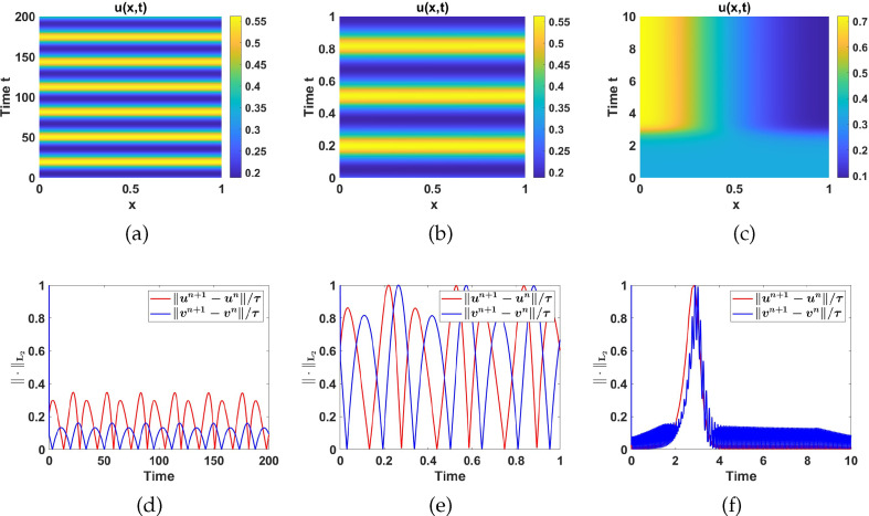
This study presents a detailed mathematical analysis of the spatio-temporal dynamics of the RhoA-GEF-H1-myosin signalling network, modelled as a coupled system of reaction-diffusion equations. By employing conservation laws and the quasi-steady state approximation, the dynamics is reduced to a tractable nonlinear system. First, we analyse the temporal system of ordinary differential equations (ODE) in the absence of spatial variation, characterizing stability, bifurcations and oscillatory behaviour through phase-plane analysis and bifurcation theory. As parameter values change, the temporal system transitions between stable dynamics; unstable steady states characterized by oscillatory dynamics; and co-existence between locally stable steady states, or co-existence between a locally stable steady state and a locally stable limit cycle. Second, we extend the analysis to the reaction-diffusion system by incorporating diffusion to the temporal ODE model, leading to a comprehensive study of Turing instabilities and spatial pattern formation. In particular, by adding appropriate diffusion to the temporal model: (i) the uniform steady state can be destabilized leading to the well-known Turing diffusion-driven instability (DDI); (ii) one of the uniform stable steady states in the bistable region can be driven unstable, while the other one remains stable, leading to the formation of travelling wave fronts; and (iii) a stable limit cycle can undergo DDI leading to the formation of spatial patterns. More importantly, the interplay between bistability and diffusion shows how travelling wavefronts can emerge, consistent with experimental observations of cellular contractility pulses. Theoretical results are supported by numerical simulations, providing key insights into the parameter spaces that govern pattern transitions and diffusion-driven instabilities.

Keywords: Rho-GEF-Myosin signalling network; Turing diffusion-driven instability; activator-inhibitor system; bifurcation analysis; reaction-diffusion; travelling wave front.


Conflict of interest statement

We declare we have no competing interests.

Figures

A schematic representation of the experimental model for Rho-GEF-Myosin signalling network from which mathematical equations are derived [21]
Figure 1.
A schematic representation of the experimental model for the Rho-GEF-myosin signalling network from which mathematical equations are derived [21]. In this visual representation, the symbols Ga , Ra and Ma denote the active states of GEF, Rho and myosin, while Gi , Ri and Mi signify their respective inactive states. Reaction rates are represented as k1 , k2 , k3 , k4 , k5 and k6 , and the Michaelis–Menten constants are denoted as Km1 , Km2 , Km3 and Km4 . The broken red lines represent a positive feedback loop while blue lines represent a negative feedback loop.
Numerical bifurcation results corresponding to System (2
Figure 2.
Numerical bifurcation results corresponding to system (2.3) with set 1 parameter values as listed in table 6. Plots (a) and (b) represent one-parameter bifurcation diagrams with bifurcation parameter a1 . HB stands for the Hopf bifurcation point, and the dashed black line represents the values of u and v in the unstable region, while the solid red line represents the values of u and v in the stable region. Hopf bifurcation points occur at a1=1.365 and a1=1.839 . The green loop indicates the upper and lower limits of the resultant limit cycle. (c) represents the two-parameter bifurcation diagram with bifurcation parameters a1 and a5 . The red region represents the oscillatory region, while the lime region represents the stable region.
Numerical simulations showing temporal evolution profiles
Figure 3.
Numerical simulations showing temporal evolution profiles of u(t) and v(t) corresponding to system (2.3), with set 1 parameter values as listed in table 6 with (a) a1=0.5 . (b) a1=1.5 . (c) a1=2 .
Turing instability regions in selected pairwise parameter planes
Figure 4.
Turing instability regions in selected pairwise parameter planes for different d values. All other parameters remain fixed, as indicated in table 6. The explanation of the regions is shown in table 4.
One parameter bifurcation diagrams corresponding
Figure 5.
One parameter bifurcation diagrams corresponding to (a) u* against a1 for a5=0.5 , (b) v* against a1 for a5=0.5 , (c) u* against v for a5=1,5 , (d) v* against a1 for a5=1.5 and (e) u* against a1 for a1=2 (f) v* against a1 for a5=2 . In all diagrams, LP and HB represent fold and Hopf bifurcation points, respectively.
Phase plane diagram showing that the uniform steady state
Figure 6.
(a) Phase plane diagram showing that the uniform steady state P1 is globally asymptotically stable and, (b) the u(t) and v(t) time evolution for system (2.3) corresponding to region I of figure 11 . Here a1=0.2 and a5=2 .
Phase plane diagram showing that the uniform steady state
Figure 7.
(a) Phase plane diagram showing that the uniform steady state P2 is globally asymptotically stable and, (b) the u(t) and v(t) time evolution for system (2.3) corresponding to region II shown in figure 11, Here a1=2 and a5=1 .
Phase plane diagram showing the limit cycle around the uniform steady state
Figure 8.
(a) Phase plane diagram showing the limit cycle around the uniform steady state P3 , coloured green. (b) u(t) and v(t) time evolution for system (2.3) corresponding to region III of figure 11. Here a1=4 and a5=1.5 .
Phase plane diagram showing coexistence of a L.A.S limit cycle (green loop)
Figure 9.
(a) Phase plane diagram showing coexistence of a L.A.S limit cycle (green loop) and L.A.S uniform steady state, P9 , (b) the basin of attraction for the limit cycle around the uniform steady state P7 and the steady state P9 , and (c) the u(t) and v(t) time evolution for system (2.3) corresponding to region V of figure 11. Here a1=5 and a5=1.5 together with initial conditions (0.61,3.1) and (2.1,5.5) .
Phase plane diagram showing coexistence of three uniform steady states
Figure 10.
(a) Phase plane diagram showing coexistence of three uniform steady states, P4 , P5 and P6 , (b) the basin of attraction for the uniform steady states P4 and P6 , and (c) the u(t) and v(t) time evolution for system (2.3) corresponding to region IV, shown in figure 11. Here a1=4.3 and a5=2.1 . The initial conditions for bistability are (0.6, 5) and (2.1, 5.5).
Two-parameter numerical bifurcation analysis results corresponding to System
Figure 11.
Two-parameter numerical bifurcation analysis results corresponding to system (2.3) with a1 and a5 as bifurcation parameters and set 2 parameter values as listed in table 6. I, single non-Turing uniform steady state; II, single Turing-type uniform steady state; III, single unstable uniform steady state; IV, three uniform steady states with one stable and the other unstable (bistable region); V, three uniform steady states with two unstable and one stable.
Plots of: (a) , and (b) numerical solutions
Figure 12.
Plots of: (a) u(x,t) , and (b) v(x,t) numerical solutions, and (c) the L2 -norm of the discrete time-derivative of u(x,t) and v(x,t) at different time points. Parameters are chosen from region I while the rest are as listed in table 6 with d=10 and γ=500 .
Plot of: (a) the contours
Figure 13.
Plot of: (a) the contours of u(x,t) numerical solutions and (b) the L2 norms of the discrete time-derivatives of u(x,t) and v(x,t) . The parameter values are chosen from region II while the rest are listed in table 6 with d=10 and γ=500 . The numerical solutions qualitatively mirror the profile of the eigenfunction.
Numerical simulation results corresponding to System (2
Figure 14.
Numerical simulation results corresponding to system (2.1) with parameter values in region II, d = 10 and varying γ.(a) u(x,t) , numerical solution and (b) the L2 norms of the discrete time-derivative of u(x,t) and v(x,t) , with γ=1000 , while (c) and (d) are respectively the contour plot of u(x,t) and the L2 norms of the discrete time-derivative of u(x,t) and v(x,t) , when γ=5000 . The profiles of numerical solutions qualitatively reproduce the profiles of the eigenfunctions as predicted by the linear stability theory.
Numerical simulation results corresponding to System
Figure 15.
Numerical simulation results corresponding to system (2.1) with parameter values in region III and d = 50.(a)–(c) Contour plots of u(x,t) for γ=1 , γ=100 and γ=250 respectively, and (d)–(e) the respective L2 -norm of the discrete time-derivative of u(x,t) and v(x,t) .
Plots of (a) the period and (b) amplitude, against
Figure 16.
Plots of (a) the period and (b) amplitude, against γ respectively, corresponding to the limit cycle in region III, with d=50 .
Plots of: (a) , and (b) solutions exhibiting travelling wave fronts and spatial profiles
Figure 17.
Plots of: (a) u(x,t) , and (b) v(x,t) solutions exhibiting travelling wave fronts and spatial profiles of (c) u(x,t) and (d) v(x,t) at different time points. Parameters are chosen from region IV while the rest are listed in table 6 together with d=50 and γ=200 .
Plots of: (a) contour plot of , exhibiting the formation of spatially inhomogeneous patterns
Figure 18.
Plots of: (a) contour plot of u(x,t) , exhibiting the formation of spatially inhomogeneous patterns. (b) Plot of the L2 -norm of the discrete time derivatives of u(x,t) and v(x,t) . Parameters are chosen from region IV while the rest are listed in table 6 together with d=50 , γ=200 and L=10 .
Plots of: (a) , and (b) solutions exhibiting travelling wave fronts.
Figure 19.
Plots of: (a) u(x,t) , and (b) v(x,t) solutions exhibiting travelling wave fronts. (c) –(d) Snapshots of the spatial profiles of u(x,t) and v(x,t) at different time points. Parameters are chosen from region V while the rest are listed in table 6 together with d=50 , γ=200 .
A schematic representation showing the flow of solutions when approaching
Figure 20.
A schematic representation showing the flow of solutions when approaching the boundaries of the invariant set E .
Plots illustrating the interval
Figure 21.
Plots illustrating the interval kl2<k2<kr2 in which (a) q(k2)<0 and (b) Re λ(k2)>0 hold for d<dc , d=dc , and d>dc . Here, dc=5.84 , γ=200 , a7=16 , in addition to the other parameters from set 2 as listed in table 6.
Plots for and Re showing the excited modes between
Figure 22.
Plots for q(k2) and Re λ(k2) showing the excited modes between kl2 and kr2 . (a) – (b): one excited mode, with γ=200 . (c) –(d): one excited mode, γ=1500 . (e) – (f): three excited modes, γ=5000 . See table 7 for the summary of excited modes.

References

    1. Ridley A, Peckham M, Clark P. 2004. Cell motility: from molecules to organisms. Chichester, England, UK: John Wiley & Sons.
    1. Franz CM, Jones GE, Ridley AJ. 2002. Cell migration in development and disease. Dev. Cell 2 , 58. (10.1016/s1534-5807(02)00120-x) - DOI - PubMed
    1. Kedrin D, van Rheenen J, Hernandez L, Condeelis J, Segall JE. 2007. Cell motility and cytoskeletal regulation in invasion and metastasis. J. Mammary Gland Biol. Neoplasia 12 , 143–152. (10.1007/s10911-007-9046-4) - DOI - PubMed
    1. Juma VO, Sainz‐DeMena D, Sánchez MT, García‐Aznar JM. 2023. Effects of tumour heterogeneous properties on modelling the transport of radiative particles. Int. J. Numer. Methods Biomed. Eng. 39 , e3760. (10.1002/cnm.3760) - DOI - PubMed
    1. Wang W, Goswami S, Sahai E, Wyckoff JB, Segall JE, Condeelis JS. 2005. Tumor cells caught in the act of invading: their strategy for enhanced cell motility. Trends Cell Biol. 15 , 138–145. (10.1016/j.tcb.2005.01.003) - DOI - PubMed

LinkOut - more resources