

Impact of High Insertion Torque on Implant Surface Integrity
- PMID: 40200410
- PMCID: PMC11978974
- DOI: 10.1111/cid.70030
Impact of High Insertion Torque on Implant Surface Integrity
Abstract
Introduction: The long-term success of dental implants depends on the preservation of supporting tissues over time. Recent studies have highlighted the release of titanium particles as a potential etiology for the onset and progression of peri-implant diseases modulated by inflammatory biomarkers. This study provides a comprehensive analysis of surface changes associated with high insertion torque placement.
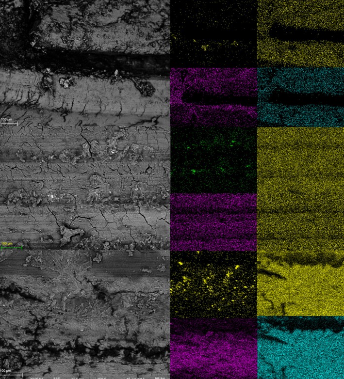
Methods: Three groups of cylindrical threaded dental implants, each representing different surface topographies produced by anodization or a combination of grit-blasting and acid-etching processes, were inserted into fresh cow rib bone blocks used to mimic human jaws. Individual bone blocks were fabricated with a dimension of 20 × 15 × 15 mm, randomly assigned to the three implant groups. Prior to dental implant placement, the bone blocks were divided in half to facilitate implant removal without introducing additional damage. The drilling protocol was modified, excluding the final drill recommended by the manufacturer to ensure higher insertion torque values during the procedure. Dental implants were removed from the bone blocks and processed for analysis. Surface roughness was characterized using interferometry on the same area before and after insertion. Scanning electron microscopy (SEM) with a back-scattered electron detector (BSD) was employed to identify the implant surface and loose particles at the bone block interface.
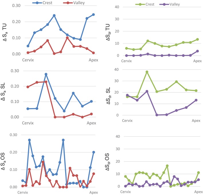
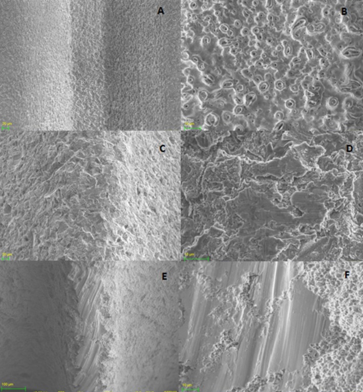
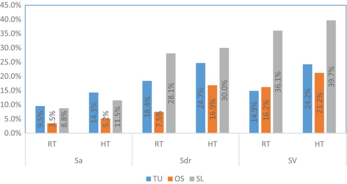
Results: The high insertion torque protocol used in this study resulted in higher insertion torque values compared to manufacturers' protocol, but no difference was observed when comparing the three implant groups. Surface roughness characterization revealed that amplitude and hybrid roughness parameters for all three groups were lower after insertion. The surfaces exhibiting a predominance of peaks (Ssk [skewness] > 0) associated with higher structures (height parameters) showed greater damage at the crests of the threads, while no changes were observed in the valleys of the threads. SEM-BSD images revealed loose titanium particles at the bone blocks interface, predominantly at the crestal cortical bone level.
Conclusions: High insertion torque resulted in surface damage at the crests of threads, which subsequently led to the release of titanium particles primarily at the bone crest. The initial release of titanium particles during implant insertion at the bone-implant interface warrants further exploration as a potential cofactor for marginal bone loss.
Keywords: biomaterials; implant design; implant surface; surface properties; surface topography.
© 2025 The Author(s). Clinical Implant Dentistry and Related Research published by Wiley Periodicals LLC.
Conflict of interest statement
The authors declare no conflicts of interest.
Figures


Similar articles
-
Surface Damage on Dental Implants with Release of Loose Particles after Insertion into Bone.Clin Implant Dent Relat Res. 2015 Aug;17(4):681-92. doi: 10.1111/cid.12167. Epub 2013 Nov 28. Clin Implant Dent Relat Res. 2015. PMID: 24283455 Free PMC article.
-
Integrity of implant surface modifications after insertion.Int J Oral Maxillofac Implants. 2014 Jan-Feb;29(1):97-104. doi: 10.11607/jomi.3259. Int J Oral Maxillofac Implants. 2014. PMID: 24451859
-
Effect of macrogeometry and bone type on insertion torque, primary stability, surface topography damage and titanium release of dental implants during surgical insertion into artificial bone.J Mech Behav Biomed Mater. 2021 Jul;119:104515. doi: 10.1016/j.jmbbm.2021.104515. Epub 2021 Apr 19. J Mech Behav Biomed Mater. 2021. PMID: 33932754
-
[The role of surface roughness in promoting osteointegration].Refuat Hapeh Vehashinayim (1993). 2003 Jul;20(3):8-19, 98. Refuat Hapeh Vehashinayim (1993). 2003. PMID: 14515625 Review. Hebrew.
-
Surface Modifications of Commercial Dental Implant Systems: An Overview.J Long Term Eff Med Implants. 2023;33(2):71-77. doi: 10.1615/JLongTermEffMedImplants.2022042612. J Long Term Eff Med Implants. 2023. PMID: 36734929 Review.
References
-
- Rea M., Botticelli D., Ricci S., Soldini C., Gonzalez Gonzalez G., and Lang N. P., “Influence of Immediate Loading on Healing of Implants Installed With Different Insertion Torques—An Experimental Study in Dogs,” Clinical Oral Implants Research 26, no. 1 (2015): 90–95, 10.1111/clr.12305. - DOI - PubMed
-
- Esposito M., Grusovin M. G., Willings M., Coulthard P., and Worthington H. V., “The Effectiveness of Immediate, Early, and Conventional Loading of Dental Implants: A Cochrane Systematic Review of Randomized Controlled Clinical Trials,” International Journal of Oral & Maxillofacial Implants 22, no. 6 (2007): 893–904. - PubMed
MeSH terms
Substances
LinkOut - more resources
Full Text Sources
Miscellaneous
