. 2022 Aug 16;2(9):2200030.
doi: 10.1002/smsc.202200030. eCollection 2022 Sep.

Strategies of Anode Design for Seawater Electrolysis: Recent Development and Future Perspective

Affiliations

Strategies of Anode Design for Seawater Electrolysis: Recent Development and Future Perspective

Tanveer Ul Haq et al. Small Sci. .

Abstract

Compared with freshwater splitting, seawater electrolysis has more spaces to be explored, which is primarily attributed to the additional critical catalytic challenges of the competition between anodic oxygen evolution reaction (OER) and chlorine chemistry, deep corrosion, and site blocking due to the presence of chloride ions and insoluble particulate in seawater. However, if direct seawater electrolysis can be realized, it would revolutionize the energy and environmental sectors. In this review, the current effective strategies are summarized, including electronic modulation, oxygen vacancies creation, amorphous and porous structure design, corrosion-resistant passive layer decoration, and creating strong catalyst-support interactions. The review also provides insights for seawater electrolysis on rational design of the OER catalyst with high selectivity, activity, corrosion resistance, chemical, and mechanical durability. Beyond the progress made to date, a perspective in the fabrication of high-performance anodes for direct seawater electrolysis is also proposed. Collectively, this review will shed light on the rational design of a viable anode for massive and sustainable hydrogen fuel production from immense seawater.

Keywords: anode designs; electronic structures; hydrogen production; nanomaterials; seawater electrolysis.


Conflict of interest statement

The authors declare no conflict of interest.

Figures

Figure 1
Figure 1
Scheme for anode characteristics to improve efficiency of direct seawater electrolysis.
Figure 2
Figure 2
OER mechanism. a) Single‐site mechanism and b) dual‐site mechanism. Reproduced under the terms of the CC‐BY 4.0 license.[ 25 ] Copyright 2019, The Authors, published by Springer Nature.
Figure 3
Figure 3
a) The Pourbaix diagram for simulated seawater containing 0.5 m NaCl aqueous solution where the absence of other chlorine sources ensured that the total chlorine species is 0.5 m. The water oxidation electrode potential has also been included, presuming oxygen partial pressure equal to 0.021 MPa. Two red points demonstrate the applied potential needed for Ni‐Fe LDH to deliver the geometric activity of 10 mA cm−2 after 1 h chronopotentiometry in 0.1 m KOH with 0.5 m NaCl (pH 13; lower right side) and 0.3 m borate buffer with 0.5 m NaCl (pH 9.2; upper right side). The area colored with light blue shows the proposed design criterion. b) The kinetic overpotential limit for OER catalyst as a fundction of pH has been calculated from the thermodynamic Pourbaix diagram to get 100% OER selectivity. The three possible Cl oxidation reactions have been considered to obtain these standard potential values. The dashed area indicated the thermodynamic selectivity of OER while above the line Cl oxidation reactions have been thermodynamically favorable. Reproduced with permission.[ 30 ] Copyright 2016, Wiley‐VCH.
Figure 4
Figure 4
a,b) Scanning electron microscopy (SEM) images of Co/Ni‐doped defect‐rich Cu‐based oxides and Ni/Co‐doped defect‐rich Cu‐based sulfides after long‐term electrolysis in natural seawater. The postcharacterization reveals the white residue embedded in the interior part of the cathode and covering layer and structural cracks on the anode surface. c,d) The systematic models for cathode and anode, respectively, have shown the OER degradation mechanism. Reproduced with permission.[ 38 ] Copyright 2021, Elsevier.
Figure 5
Figure 5
Au–Gd–Co2B@TiO2 catalyst for seawater splitting. a,b) OER polarization curve. c) Corrosion potential and corrosion current density and d) FE. Reproduced with permission.[ 41 ] Copyright 2021, Elsevier. CoP@FeOOH catalyst for seawater splitting. (a) OER polarization curves and (b) Tafel slop values. Reproduced with permission.[ 42 ] Copyright 2021, Elsevier
Figure 6
Figure 6
a) High‐throughput DFT simulations to establish the thermodynamically stable structure by randomly substituting the Ru with Ir or Sr. b) Different metal stoichiometry modified the OER overpotential, the red zone shows the Sr–Ir–Ru atomic ratio with the lowest overpotential. c) Pourbaix diagram of Sr1Ru6Ir1O16 and Sr2Ru5Ir1O16 oxide represents that Sr1Ru6Ir1O16 has been thermodynamically stable in OER region. Reproduced with permission.[ 44 ] Copyright 2021, American Chemical Society.
Figure 7
Figure 7
Sketch representing the different OER efficiency of Mn2,O3, and MnO2 electrodes. M x –O y  = Co3O4, Fe2O3.The middle panel comprises a schematic energy band diagram of Co3O4–Mn2O3, Co3O4–MnO2, Fe2O3–Mn2O3, Fe2O3–MnO2, and systems, with estimated energy levels concerning the RHE) scale, CB represents the conduction band while VB represents the valance band. Reproduced with permission.[ 51 ] Copyright 2020, Elsevier.
Figure 8
Figure 8
Systematic representation of O 2p orbital bond formation with the highest occupied d‐state of TMO. The VB of the most stable insulators or semiconductor TMO comprises the d‐state of TM cation and the O 2p state. a,b) n‐type TMO bonding with O 2p, where highest occupied filled state at lower energy relative to Fermi level and antibonding states are usually filled. The surface oxygen vacancies create a bandgap caused by unpaired d‐electrons and lead to stronger adsorption of O due to uplift of d‐TMO antibonding states relative to Fermi level. c,d) p‐type TMO bonding with O 2p where highest occupied states are much closer to Fermi level, and antibonding states are less populated than n‐type TMO─decreasing the highest occupied states relative to Fermi level, causing the more filling of antibonding states and decreasing the interaction. The difference between the highest occupied state and Fermi level defines the electronic origin and surface reactivity of TMO. Reproduced with permission.[ 55 ] Copyright 2016, American Chemical Society.
Figure 9
Figure 9
OER mechanism on the surface of Mo–Ni foam‐supported, S‐doped Ni–Fe LDH. Reproduced with permission.[ 56 ] Copyright 2021, Elsevier.
Figure 10
Figure 10
a) SO4 2− protecting layer has been fabricated to protect the metal substrate from chloride corrosion in seawater electrolysis. Reproduced with permission.[ 64 ] Copyright 2021, Wiley‐VCH. b) Illustration of the multilayered anode composed of the Ni–Fe alloys substrate for structural support, NiFe–B alloys as a corrosion‐proof layer, and surface‐oxidized Ni–Fe–B as OER active layer shows higher selectivity and corrosion resistance in seawater electrolysis. Reproduced with permission.[ 32 ] Copyright 2021, Wiley‐VCH. c) Flow diagram representing the construction of bilayer structure comprising Mg‐inserted, MnO2‐doped Co (upper) and Co (OH)2 (under). The steps are electrodeposition of Co (OH)2 under layer and electrodeposition of cetyltrimethylammonium Co–MnO2 followed by ion exchange process for Mg intercalation. Reproduced with permission.[ 66 ] Copyright 2020, American Chemical Society.
Figure 11
Figure 11
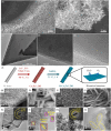
SEM images of a) Ni foam‐supported Co‐ZIF/L precursor and b) Ru‐incorporated amorphous Co oxide (Ru–Co–O x /NF). c–e) TEM images of Ru–Co–O x /NF. Reproduced with permission.[ 80 ] Copyright 2021, Wiley‐VCH. f) Systematic Illustration of the formation of partially amorphous B–Co2Fe–LDH comprising two steps of water bath reaction followed by chemical reduction of the oxide with NaBH4. g,h) SEM images of Co2Fe–LDH, i,j) SEM images of B‐doped Co2Fe–LDH, k) TEM, l) HRTEM images of Co2Fe–LDH, and m) TEM and n) HRTEM images of B–Co2Fe–LDH. Reproduced with permission.[ 73 ] Copyright 2021, Elsevier
Figure 12
Figure 12
SEM images of a) bare Ni foam, b–d) S–(Ni, Fe)–OOH with different magnifications, e) surface topography, and f,g) TEM images, h) selected area electron diffraction pattern, i) HRTEM image of S–(Ni, Fe)–OOH, j) scanning transmission electron microscopy image, and elemental mapping. Reproduced with permission.[ 84 ] Copyright 2020, Royal Society of Chemistry.
Figure 13
Figure 13
a) Systematic representation of the formation of the polypyrrole (PPy) and tannic acid (TA)‐modified hollow MIL‐88(Fe‐Co‐Ni) (HMIL‐88@PPY‐TA) on Ni foam, a). SEM images of b) MIL‐88(Fe‐Co‐Ni) c) and HMIL‐88@PPY‐TA d). TEM images of MIL‐88(Fe‐Co‐Ni) e) and HMIL88@PPY‐TA. Reproduced with permission.[ 86 ] Copyright 2022, Elsevier. g,h) SEM images reveal the mesoporous structure of natural balsa wood with open and aligned microchannels, i–k) SEM images of wood aerogel with lamellar arch‐fashioned layer demonstrating the thinner thickness compared with natural wood. l) SEM images of well aligned cellulose nanofiber with rough and intricate structure. Reproduced with permission.[ 88 ] Copyright 2021, Elsevier.
Figure 14
Figure 14
Gd–Mn3O4@CuO–Cu(OH)2 catalyst for seawater splitting. OER polarization curve recorded before and after 1000th cycles in a) 1 m KOH and b) 1 m KOH +Seawater. c) Durability test at constant current density of 100 mA cm−2 in alkaline seawater. Reproduced with permission.[ 109 ] Copyright 2022, American Chemical Society.

Similar articles

Cited by

References

    1. Sun F., Qin J., Wang Z., Yu M., Wu X., Sun X., Qiu J., Nat. Commun. 2021, 12, 1. - PMC - PubMed
    1. Yu Z. Y., Duan Y., Feng X. Y., Yu X., Gao M. R., Yu S. H., Adv. Mater. 2021, 33, 2007100. - PubMed
    1. Ran J., Jaroniec M., Qiao S. Z., Adv. Mater. 2018, 30, 1704649. - PubMed
    1. Abdul Nasir J., Munir A., Ahmad N., ul Haq T., Khan Z., Rehman Z., Adv. Mater. 2021, 2105195. - PubMed
    1. Haq T. U., Haik Y., Hussain I., Rehman H. U., Al-Ansari T. A., ACS Appl. Mater. Interfaces 2021, 13, 468. - PubMed

LinkOut - more resources