

Electrohydrodynamic Jet Printing: Introductory Concepts and Considerations
- PMID: 40213534
- PMCID: PMC11935840
- DOI: 10.1002/smsc.202100073
Electrohydrodynamic Jet Printing: Introductory Concepts and Considerations
Abstract
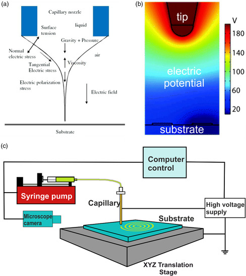
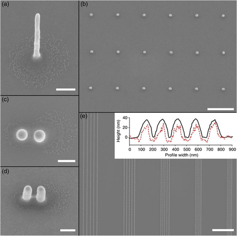
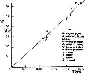
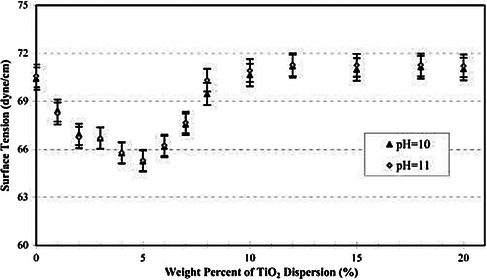
Electrohydrodynamic (EHD) jet printing is an emerging technique in the field of additive manufacturing. Due to its versatility in the inks it can print, and most importantly, the printing resolution it can achieve, it is rapidly gaining favor for application in the manufacture of electronic devices, sensors, and displays among others. Although it is an affordable and accessible manufacturing process, it does require excellent operational understanding to achieve high resolution printing of up to 50 nm as reported in literature. In this review, three main aspects are considered, namely, the ink properties, the printer system itself (including design, nozzle dimensions, applied potential, and others), and the substrate onto which printing is being carried out. Knowing how all these factors can be manipulated and brought together allows the users of EHD printing to achieve extraordinary resolution and consistent results. The review is concluded with a brief discussion on where one can see the potential for development in this field of research.
Keywords: electrohydrodynamic jet printing; ink properties; inkjet printing nozzles; process parameters for jet printing; substrate properties for inkjet printing.
© 2021 The Authors. Small Science published by Wiley‐VCH GmbH.
Conflict of interest statement
The authors declare no conflict of interest.
Figures


Similar articles
-
High-Resolution, Transparent, and Flexible Printing of Polydimethylsiloxane via Electrohydrodynamic Jet Printing for Conductive Electronic Device Applications.Polymers (Basel). 2022 Oct 17;14(20):4373. doi: 10.3390/polym14204373. Polymers (Basel). 2022. PMID: 36297952 Free PMC article.
-
Temperature-Sensing Inks Using Electrohydrodynamic Inkjet Printing Technology.Materials (Basel). 2021 Sep 27;14(19):5623. doi: 10.3390/ma14195623. Materials (Basel). 2021. PMID: 34640024 Free PMC article.
-
Silver Nano-Inks Synthesized with Biobased Polymers for High-Resolution Electrohydrodynamic Printing Toward In-Space Manufacturing.ACS Appl Mater Interfaces. 2024 Aug 21;16(33):44225-44235. doi: 10.1021/acsami.4c07592. Epub 2024 Jul 30. ACS Appl Mater Interfaces. 2024. PMID: 39079046
-
Designs and applications of electrohydrodynamic 3D printing.Int J Bioprint. 2018 Dec 26;5(1):172. doi: 10.18063/ijb.v5i1.172. eCollection 2019. Int J Bioprint. 2018. PMID: 32782979 Free PMC article. Review.
-
Mechanisms and modeling of electrohydrodynamic phenomena.Int J Bioprint. 2018 Dec 28;5(1):166. doi: 10.18063/ijb.v5i1.166. eCollection 2019. Int J Bioprint. 2018. PMID: 32782978 Free PMC article. Review.
Cited by
-
Application of pulse width modulation control in EHD waveform to optimize printing performance.Microsyst Nanoeng. 2025 Jun 9;11(1):117. doi: 10.1038/s41378-025-00901-x. Microsyst Nanoeng. 2025. PMID: 40490474 Free PMC article.
-
Integrated Additive Manufacturing of TGV Interconnects and High-Frequency Circuits via Bipolar-Controlled EHD Jetting.Micromachines (Basel). 2025 Aug 2;16(8):907. doi: 10.3390/mi16080907. Micromachines (Basel). 2025. PMID: 40872414 Free PMC article.
-
Bidirectional mechanisms and emerging strategies for implantable bioelectronic interfaces.Bioact Mater. 2025 Jun 19;52:634-667. doi: 10.1016/j.bioactmat.2025.06.014. eCollection 2025 Oct. Bioact Mater. 2025. PMID: 40607118 Free PMC article. Review.
-
Printed Strain Sensors for Motion Recognition: A Review of Materials, Fabrication Methods, and Machine Learning Algorithms.IEEE Open J Eng Med Biol. 2023 Nov 6;6:353-381. doi: 10.1109/OJEMB.2023.3330290. eCollection 2025. IEEE Open J Eng Med Biol. 2023. PMID: 40657052 Free PMC article.
-
Facile Fabrication of Large-Area and High-Quality Organic-Inorganic Hybrid Perovskite Ferroelectric Films Through Electrohydrodynamic Printing.Adv Sci (Weinh). 2025 Jun;12(21):e2414122. doi: 10.1002/advs.202414122. Epub 2025 Apr 1. Adv Sci (Weinh). 2025. PMID: 40167187 Free PMC article.
References
-
- Onses M. S., Sutanto E., Ferreira P. M., Alleyne A. G., Rogers J. A., Small 2015, 4237. - PubMed
-
- Park J.-U., Hardy M., Kang S. J., Barton K., Adair K., Mukhopadhyay D. K., Lee C. Y., Strano M. S., Alleyne A. G., Georgiadis J. G., Ferreira P. M., Rogers J. A., Nat. Mater. 2007, 6, 782. - PubMed
-
- Ru C., Luo J., Xie S., Sun Y., Journal of Micromechanics and Microengineering, 2014, 24, 053001.
-
- Jaworek A., Sobczyk A. T., J. Electrostat. 2008, 66, 197.
LinkOut - more resources
Full Text Sources
Other Literature Sources