. 2023 Dec 23:2023:6331148.
doi: 10.1155/2023/6331148. eCollection 2023.

Applied Electric Fields Polarize Initiation and Growth of Endothelial Sprouts

Affiliations

Applied Electric Fields Polarize Initiation and Growth of Endothelial Sprouts

Anyesha Sarkar et al. J Tissue Eng Regen Med. .

Abstract

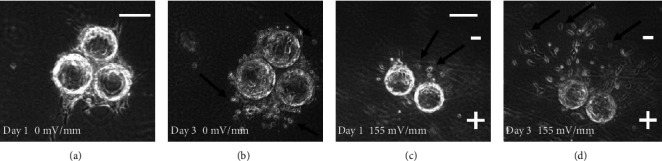
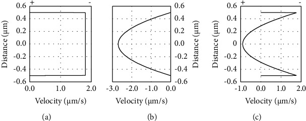
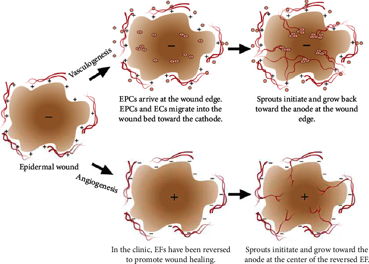
Therapeutic electric fields (EFs) are applied to the epidermis to accelerate the healing of chronic epidermal wounds and promote skin transplantation. While research has emphasized understanding the role of EFs in polarizing the migration of superficial epidermal cells, there are no reports describing the effect of EFs on polarization of the underlying vasculature. We explored the effects of EFs on the growth of endothelial sprouts, precursors to functional blood vessels. We discovered that DC EFs of the same magnitude near wounded epidermis polarize initiation, growth, and turning of endothelial sprouts toward the anode. While EFs polarize sprouts, they do not change the frequency of primary sprout or branch formation. Unidirectional electrical pulses also polarize sprouts based on their time-averaged EF magnitude. Sprout polarization occurs antiparallel to the direction of electrically driven water flow (electro-osmosis) and is consistent with the direction of sprout polarization induced by pressure-driven flow. These results support the role of EFs in controlling the direction of neovascularization during the healing of soft tissues and tissue engineering.


Conflict of interest statement

The authors have no relevant financial or nonfinancial conflicts of interest to disclose.

Figures

Figure 1
Figure 1
Experimental channel design. EFs were applied to HUVEC structures in IBIDI channel slides. A series resistor and resistance substitution box (RSB) were used to monitor and control the electric field in the channels. (a) The open channel design enabled easier exchange of media by simply removing the syringe filters. This design also provided a low-resistance pathway for fluid flow from the anode to the cathode side of the channel. (b) The closed channel design involved directly connecting the low electroendosmosis (EEO) agarose bridges to the IBIDI wells. While cathode-directed electro-osmotic flow (EOF) continues along negatively charged surfaces through the channel, fluid pressure gradients dissipate in the reverse direction through the porous fibrin matrix.
Figure 2
Figure 2
Photos of endothelial cell migration in fibrin gels in the absence of fibroblasts. (a) After one day in fibrin gel, the endothelial cells remained tightly adhered to the collagen-coated beads and small sprouts formed. (b) After three days in the absence of fibroblasts, endothelial cells had detached from the beads and migrated into the fibrin gel (black arrows). (c) In the presence of a 155 mV/mm DC EF, some cells started migrating toward the cathode in the fibrin gel (black arrows) after one day. (d) After 3 days in the EF, many of the cells had detached from the beads and migrated toward the cathode pole in the fibrin gel (black arrows) at significantly greater distances than in the absence of the EF shown in Figure 2(b) (scale bars 100 μm).
Figure 3
Figure 3
EFs direct single endothelial cell migration toward the cathode. (a–c) Trajectory plots for single migrating HUVECs in the absence and presence of applied DC EFs over a period of 4 hours. (d) HUVECs cultured on glass migrate toward the cathode in an applied EF (●); cathode is positive. When exposed to 360 mV/mm, HUVECs migrate randomly on tissue culture plastic (○) (n = 11).
Figure 4
Figure 4
Photos of endothelial sprouts. (a–c) Sprouts grow persistently away from the cell mass in the absence of applied EFs. (d–f) Sprouts grow toward the anode in the presence of DC EFs of 360 mV/mm (scale bars 100 μm).
Figure 5
Figure 5
DC EFs polarize endothelial sprouts. (a1–e1) Superimposed sprout tracings display increasing anodal polarization with EF strength (origin = white disk). Insets display the relative distribution of all sprouts for each 30° region of each condition. C: cathode; A: anode. (a2) Regional comparison of relative sprout distribution in the absence of EFs (100 • Σ sprout length per region/Σ sprout length for all regions). (b2–e2) Relative distribution of EF-exposed sprouts (red) normalized to the relative sprout distribution determined in the absence of EFs (black) for each condition. (a3) The average sprout length (μm) remains the same for all regions in the absence of EFs. (b3–e3) EFs decrease average relative sprout length (red) compared to sprouts grown simultaneously in the absence of EFs (black). (a4) Sprouts were traced using the line segment tool in ImageJ and used to determine the Δ cos θ values between the initial segment (θ1) and the final segment (θ2) of each sprout. (b4–e4) Relative average turning of EF-exposed sprouts (red) normalized to sprout turning determined in the absence of EFs (black). Cathodal turning (<1), no net turning (=1), anodal turning (>1). One-tailed t-tests were used to assess statistical significance for increased () or decreased (∘) growth or turning (one symbol, 0.002 < p < 0.02; two symbols, 0.0002 < p < 0.002; three symbols, p < 0.0002).
Figure 6
Figure 6
EFs direct sprout initiation toward the anode. (●) DC EFs significantly polarize sprout initiation toward the anode at 50 mV/mm and increase anodal initiation at 155 and 360 mV/mm. (○) Polarized initiation toward the anode at 360 mV/mm in the closed channels, where there is no net fluid flow, is not statistically different than initiation in the open channels at the same field strength (p > 0.5). (△) Pulsed EFs of 360 mV/mm with alternating direction, possessing a time-averaged EF of 0 mV/mm, showed no difference in the direction of initiation. Unidirectional pulsed EFs of 360 mV/mm with 14.3% and 50% duty cycles with time-averaged EFs of 51.4 and 180 mV/mm, respectively, significantly polarize sprout initiation toward the anode (p < 0.01 and p < 0.0001).
Figure 7
Figure 7
Cathode-directed electro-osmotic flow continues near negatively charged surfaces during zero net fluid flow in a closed channel. (a) Electro-osmotic flow toward the cathode is modelled through a 1 μm tall channel forming a plug flow profile [29]. (b) A reverse direction pressure gradient is modelled and generates a parabolic flow profile through the 1 μm tall channel with the same average volumetric flow rate. (c) Simultaneous application of both flows generates slightly reduced flow velocity next to the charged walls, and backflow through the lowest resistance pathway, the center of the channel. In vitro, fibrin gels have pore sizes ranging from 3 to 10 μm depending on preparation conditions [30, 31]. Therefore, EOF next to charged fibrin and charged sprout surfaces continues in a closed system and the pressure gradients dissipate through the low resistance center of the pores.
Figure 8
Figure 8
Sprout polarization is dependent on the time-averaged field strength. (a1–c1) Unidirectional pulsed EFs increase sprout polarization. Insets show the applied electrical waveforms beginning at 0 mV/mm. (a2–c2) Relative sprout distribution exposed to pulsed EFs (red) compared to the normalized sprout distribution determined in the absence of EFs (black). (a3–c3) Relative length of sprouts exposed to pulsed EFs (red) compared to normalized sprout length in the absence of EFs (black). (a4–c4) Sprout turning toward the anode, Δ cos θ > 1, increases with time-averaged EF. One-tailed t-tests were used to assess statistical significance for increased () or decreased (∘) growth or turning (one symbol, 0.002 < p < 0.02; two symbols, 0.0002 < p < 0.002; three symbols, p < 0.0002).
Figure 9
Figure 9
Models describing electrical sprout polarization during normal wound healing (top) and when therapeutic applied EFs are reversed (bottom). (Top) Endothelial precursor cells (EPCs) and endothelial cells (ECs) migrate toward the cathode in applied EFs and are predicted to migrate to the center of a wound based on the native electrical polarity. Initiation and growth of endothelial sprouts originating from the EPCs and ECs near the center of the wound bed will be directed back toward the edge of the wound, the electrical anode. (Bottom) Reversal of the native wound EF has also been found to increase the rate of healing of chronic epidermal wounds. Under these conditions, sprouts at the edge of the wound would initiate and grow toward the center of the wound, promoting vascularization of the wound bed.

Similar articles

Cited by

References

    1. Lovett M., Lee K., Edwards A., Kaplan D. L. Vascularization strategies for tissue engineering. Tissue Engineering Part B Reviews . 2009;15(3):353–370. doi: 10.1089/ten.teb.2009.0085. - DOI - PMC - PubMed
    1. Novosel E. C., Kleinhans C., Kluger P. J. Vascularization is the key challenge in tissue engineering. Advanced Drug Delivery Reviews . 2011;63(4-5):300–311. doi: 10.1016/j.addr.2011.03.004. - DOI - PubMed
    1. Xu K., Cleaver O. Tubulogenesis during blood vessel formation. Seminars in Cell & Developmental Biology . 2011;22(9):993–1004. doi: 10.1016/j.semcdb.2011.05.001. - DOI - PMC - PubMed
    1. Lamalice L., Le Boeuf F., Huot J. Endothelial cell migration during angiogenesis. Circulation Research . 2007;100(6):782–794. doi: 10.1161/01.res.0000259593.07661.1e. - DOI - PubMed
    1. Vavourakis V., Wijeratne P. A., Shipley R., Loizidou M., Stylianopoulos T., Hawkes D. J. A validated multiscale in-silico model for mechano-sensitive tumour angiogenesis and growth. PLoS Computational Biology . 2017;13(1) doi: 10.1371/journal.pcbi.1005259.e1005259 - DOI - PMC - PubMed

LinkOut - more resources