

A data-driven approach for real-time soft tissue deformation prediction using nonlinear presurgical simulations
- PMID: 40228178
- PMCID: PMC11996222
- DOI: 10.1371/journal.pone.0319196
A data-driven approach for real-time soft tissue deformation prediction using nonlinear presurgical simulations
Abstract
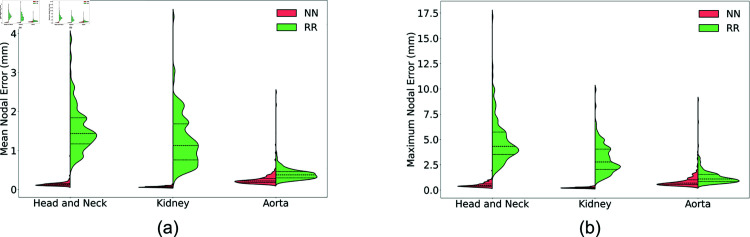
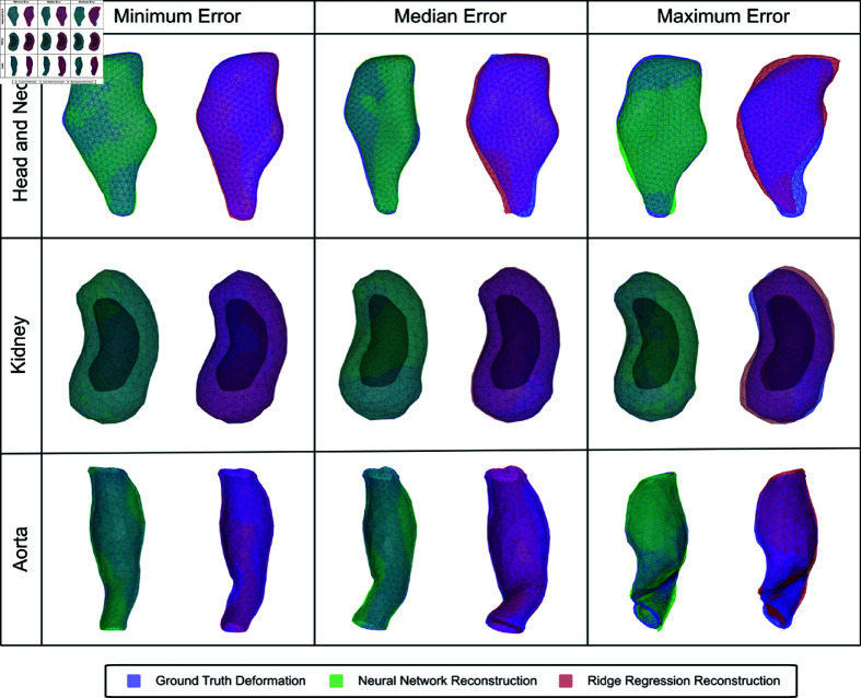
A method that allows a fast and accurate registration of digital tissue models obtained during preoperative, diagnostic imaging with those captured intraoperatively using lower-fidelity ultrasound imaging techniques is presented. Minimally invasive surgeries are often planned using preoperative, high-fidelity medical imaging techniques such as MRI and CT imaging. While these techniques allow clinicians to obtain detailed 3D models of the surgical region of interest (ROI), various factors such as physical changes to the tissue, changes in the body's configuration, or apparatus used during the surgery may cause large, non-linear deformations of the ROI. Such deformations of the tissue can result in a severe mismatch between the preoperatively obtained 3D model and the real-time image data acquired during surgery, potentially compromising surgical success. To overcome this challenge, this work presents a new approach for predicting intraoperative soft tissue deformations. The approach works by simply tracking the displacements of a handful of fiducial markers or analogous biological features embedded in the tissue, and produces a 3D deformed version of the high-fidelity ROI model that registers accurately with the intraoperative data. In an offline setting, we use the finite element method to generate deformation fields given various boundary conditions that mimic the realistic environment of soft tissues during a surgery. To reduce the dimensionality of the 3D deformation field involving thousands of degrees of freedom, we use an autoencoder neural network to encode each computed deformation field into a short latent space representation, such that a neural network can accurately map the fiducial marker displacements to the latent space. Our computational tests on a head and neck tumor, a kidney, and an aorta model show prediction errors as small as 0.5 mm. Considering that the typical resolution of interventional ultrasound is around 1 mm and each prediction takes less than 0.5 s, the proposed approach has the potential to be clinically relevant for an accurate tracking of soft tissue deformations during image-guided surgeries.
Copyright: © 2025 Liu et al. This is an open access article distributed under the terms of the Creative Commons Attribution License, which permits unrestricted use, distribution, and reproduction in any medium, provided the original author and source are credited.
Conflict of interest statement
The authors have declared that no competing interests exist.
Figures


Similar articles
-
Soft tissue deformation tracking by means of an optimized fiducial marker layout with application to cancer tumors.Int J Comput Assist Radiol Surg. 2020 Feb;15(2):225-237. doi: 10.1007/s11548-019-02075-0. Epub 2019 Oct 12. Int J Comput Assist Radiol Surg. 2020. PMID: 31606792
-
A GPU based high-resolution multilevel biomechanical head and neck model for validating deformable image registration.Med Phys. 2015 Jan;42(1):232-43. doi: 10.1118/1.4903504. Med Phys. 2015. PMID: 25563263
-
Fast computation of soft tissue thermal response under deformation based on fast explicit dynamics finite element algorithm for surgical simulation.Comput Methods Programs Biomed. 2020 Apr;187:105244. doi: 10.1016/j.cmpb.2019.105244. Epub 2019 Nov 27. Comput Methods Programs Biomed. 2020. PMID: 31805458
-
Minimizing magnetic resonance image geometric distortion at 7 Tesla for frameless presurgical planning using skin-adhered fiducials.Med Phys. 2023 Feb;50(2):694-701. doi: 10.1002/mp.16035. Epub 2022 Nov 12. Med Phys. 2023. PMID: 36301228 Review.
-
Neural Network Approaches for Soft Biological Tissue and Organ Simulations.J Biomech Eng. 2022 Dec 1;144(12):121010. doi: 10.1115/1.4055835. J Biomech Eng. 2022. PMID: 36193891 Free PMC article. Review.
References
-
- Radiological Society of North America. Fiducial marker placement; 2023. Available from: https://www.radiologyinfo.org/en/info/fiducial-marker#:~:text=The
MeSH terms
LinkOut - more resources
Full Text Sources
