Review
. 2025 May 19;54(10):4948-4972.
doi: 10.1039/d4cs00604f.

State-of-the-art and perspectives of hydrogen generation from waste plastics

Affiliations
Review

State-of-the-art and perspectives of hydrogen generation from waste plastics

Feng Niu et al. Chem Soc Rev. .

Abstract

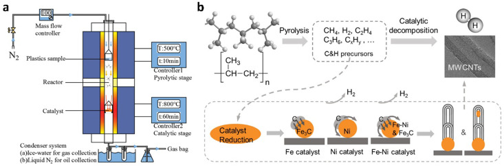
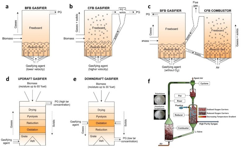
Waste plastic utilization and hydrogen production present significant economic and social challenges but also offer opportunities for research and innovation. This review provides a comprehensive analysis of the latest advancements and innovations in hydrogen generation coupled with waste plastic recycling. It explores various strategies, including pyrolysis, gasification, aqueous phase reforming, photoreforming, and electrocatalysis. Pyrolysis and gasification in combination with catalytic reforming or water gas-shift are currently the most feasible and scalable technologies for hydrogen generation from waste plastics, with pyrolysis operating in an oxygen-free environment and gasification in the presence of steam, though both require high energy inputs. Aqueous phase reforming operates at moderate temperatures and pressures, making it suitable for oxygenated plastics, but it faces challenges related to feedstock limitations, catalyst costs and deactivation. Photoreforming and electrocatalytic reforming are emerging, sustainable methods that use sunlight and electricity, respectively, to convert plastics into hydrogen. Still, they suffer from low efficiency, scalability issues, and limitations to specific plastic types like oxygenated polymers. The challenges and solutions to commercializing plastic-to-hydrogen technologies, drawing on global industrial case studies have been outlined. Maximizing hydrogen productivity and selectivity, minimizing energy consumption, and ensuring stable operation and scaleup of plastic recycling are crucial parameters for achieving commercial viability.


Conflict of interest statement

There are no conflicts to declare.

Figures

Fig. 1
Fig. 1. (a) Plastic waste use by application in million tons (Mt), Baseline scenario, Global Plastics Outlook: Policy Scenarios to 2060, https://www.oecd-ilibrary.org/ (b) Evolution of the number of publications dedicated to hydrogen and plastic recycling. Search results in Web of Science using “waste plastic” and “hydrogen” as search items (March 12, 2025).
Fig. 2
Fig. 2. Hydrogen production from waste plastics upcycling through different strategies.
Fig. 3
Fig. 3. Schematic depiction of reaction apparatus and processes for conventional pyrolysis-catalytic reforming. (a) A tandem two-stage reactor system. Reproduced with permission. Copyright 2021, Elsevier. (b) Pyrolysis and catalytic decomposition of PP for H2 and CNTs production with Fe/Ni catalyst. Reproduced with permission. Copyright 2020, Elsevier.
Fig. 4
Fig. 4. (a) Schematic diagram of the μ-reactor-GC/MS-FID-TCD system used for pyrolysis and catalytic upgrading of HDPE. Reproduced with permission. Copyright 2023, American Chemical Society. (b)–(d) Pyrolysis-catalysis of waste plastics to H2 and CNTs using a modified stainless-steel 316 catalyst. Reproduced with permission. Copyright 2023, Natl Acad Sciences.
Fig. 5
Fig. 5. Reactor configurations for pyrolysis and in-line catalytic steam reforming of biomass and waste plastics: (a) fixed bed/fixed bed, (b) fluidized bed/fixed bed, (c) screw kiln/fixed bed, (d) fluidized bed/entrained flow/fixed bed, (e) spouted bed/fluidized bed, and (f) spouted bed/fixed bed. Reproduced with permission. Copyright 2021, American Chemical Society.
Fig. 6
Fig. 6. (a) A schematic showing the typical flash Joule heating process used to convert waste plastic into flash H2. (b) A photo of the system to collect the gases evolved by FJH deconstruction of PE. (c) The relationship between initial sample resistance, H2 yield, and efficiency. Reproduced with permission. Copyright 2023, Wiley-VCH.
Fig. 7
Fig. 7. (a) The photothermal catalytic pyrolysis system. (b) Effects of catalyst on the gas yield of photothermal catalytic pyrolysis of LDPE. (a) and (b) Reproduced with permission. Copyright 2022, Elsevier. (c) Reaction mechanism for light-induced growth of CNTs and H2 production in photothermal catalytic pyrolysis of LDPE. (d) The comparison of the gas content for solar (S) and traditional (T) pyrolysis of LDPE at 500 °C. (c) and (d) Reproduced with permission. Copyright 2023, Elsevier.
Fig. 8
Fig. 8. (a) Non-thermal plasma/catalytic reactor. Reproduced with permission. Copyright 2023, Elsevier. (b) A two-stage fixed bed system for plasma-catalytic pyrolysis. (c) Influence of plasma and catalyst on PP pyrolysis product distribution, gas and oil compositions. (b) and (c) Reproduced with permission. Copyright 2022, Elsevier.
Fig. 9
Fig. 9. (a) The designed novel one-step microwave-initiated catalytic deconstruction of plastic waste to H2 and MWCNTs compared to the traditional two-step pyrolysis and gasification process. (b) The experimental set-up and reaction system configuration. (c) A time-on-stream analysis shows gas evolution as a function of the time of the microwave-initiated decomposition of HDPE. (a)–(c) Reproduced with permission. Copyright 2020, Springer Nature. (d) The mechanism of H2 production by microwave pyrolysis of PE with the assistance of carbon fiber cloth. Reproduced with permission. Copyright 2023, Elsevier.
Fig. 10
Fig. 10. Main reactions and steps of plastic gasification process.
Fig. 11
Fig. 11. Different types of gasification reactors. Bubbling fluidized bed (a), circulating fluidized bed (b), dual fluidized beds (c), updraft fixed bed (d), and downdraft fixed bed (e). Reproduced with permission. Copyright 2021, Elsevier. (f) Scheme of chemical looping gasification process. Copyright 2024, Elsevier.
Fig. 12
Fig. 12. (a) One-pot H2 production from PET upcycling by aqueous phase reforming. Reproduced with permission. Copyright 2023, American Chemical Society. (b) Time course plot of H2 yield for the one-pot depolymerization of t-PET. (c) H2 yield for the depolymerization of different plastics. (d) The proposed reaction pathway. (b)–(d) Reproduced with permission. Copyright 2023, Wiley-VCH.
Fig. 13
Fig. 13. (a) Endothermic and exothermic water splitting and photoreforming of waste plastics. (b) Mechanistic pathways of waste plastics photoreforming. Reproduced with permission. Copyright 2023, American Chemical Society.
Fig. 14
Fig. 14. (a) Diagram of the photoreforming process with a CdS/CdOx QD photocatalyst in alkaline aqueous solution. (b) H2 yields for photoreforming of different plastics. Conditions: powdered plastics (50 mg mL−1 PLA, 25 mg mL−1 PET, PET bottle, or PUR) freshly prepared (no pre-treatment) or pre-treated in 10 M aq. NaOH (2 mL). (a) and (b) Reproduced with permission. Copyright 2018, Royal Society of Chemistry. (c) Schematic diagram of photoreforming using a CNx|Ni2P photocatalyst. (d) Photograph of the batch reactor. (c) and (d) Reproduced with permission. Copyright 2019, American Chemical Society. (e) Schematic diagram of large-scale panel experiments in a flow reactor. Reproduced with permission. Copyright 2020, Wiley-VCH. (f) The calculated interaction energies between PE and TiO2 surface before and after plasma treatment. Reproduced with permission. Copyright 2023, Wiley-VCH. (g) Overview of PEC waste reforming system in the two-compartment configuration. Reproduced with permission. Copyright 2022, Wiley-VCH.
Fig. 15
Fig. 15. (a) Conventional and electrocatalytic routes for PET recycling to commodity chemicals and H2 fuel. Reproduced with permission. Copyright 2021, Springer Nature. (b) Photograph and schematic illustration of the stacked membrane-free flow electrolyzer. Reproduced with permission. Copyright 2023, American Chemical Society. (c) The solar thermo-coupled electrochemical set-up for indoor experiment. Reproduced with permission. Copyright 2020, Elsevier.
None
Feng Niu
None
Da Chen
None
Yuexiang Huang
None
Vitaly V. Ordomsky
None
Andrei Y. Khodakov
None
Kevin M. Van Geem

Similar articles

References

    1. Chaudhary K. Bhardvaj K. Chaudhary A. Fuel. 2024;358:130090. doi: 10.1016/j.fuel.2023.130090. - DOI
    1. Zhou S. Q. Shang L. Zhao Y. X. Shi R. Waterhouse G. I. N. Huang Y. C. Zheng L. R. Zhang T. R. Adv. Mater. 2019;31:1900509. - PubMed
    1. Zhao J. J. Tu Z. K. Chan S. H. Int. J. Hydrogen Energy. 2024;78:721–730.
    1. Tang D. Tan G. L. Li G. W. Liang J. G. Ahmad S. M. Bahadur A. Humayun M. Ullah H. Khan A. Bououdina M. J. Energy Storage. 2023;64:107196. doi: 10.1016/j.est.2023.107196. - DOI
    1. Barokh H. Siavashi M. Int. J. Hydrogen Energy. 2024;83:1294–1308. doi: 10.1016/j.ijhydene.2024.07.365. - DOI

LinkOut - more resources