. 2025 Jun;12(22):e2417143.
doi: 10.1002/advs.202417143. Epub 2025 Apr 16.

Covalently Interlocked Electrode-Electrolyte Interface for High-Energy-Density Quasi-Solid-State Lithium-Ion Batteries

Affiliations

Covalently Interlocked Electrode-Electrolyte Interface for High-Energy-Density Quasi-Solid-State Lithium-Ion Batteries

Dong-Yeob Han et al. Adv Sci (Weinh). 2025 Jun.

Abstract

Quasi-solid-state batteries (QSSBs) are attracting considerable interest as a promising approach to enhance battery safety and electrochemical performance. However, QSSBs utilizing high-capacity active materials with substantial volume fluctuations, such as Si microparticle (SiMP) anodes and Ni-rich cathodes (NCM811), suffer from unstable interfaces due to contact loss during cycling. Herein, an in situ interlocking electrode-electrolyte (IEE) system is introduced, leveraging covalent crosslinking between acrylate-functionalized interlocking binders on active materials and crosslinkers within the quasi-solid-state electrolyte (QSSE) to establish a robust, interconnected network that maintains stable electrode-electrolyte contact. This IEE system addresses the limitations of liquid electrolyte and QSSE configurations, evidenced by low voltage hysteresis in (de)lithiation peaks over 200 cycles, stable interfacial resistance throughout cycling, and the absence of void formation. A pressure-detecting cell kit further confirms that the IEE system exhibits lower pressure changes during cycling without any voltage fluctuations from contact loss. Moreover, the SiMP||NCM811 full cell with the IEE system demonstrates superior electrochemical performance, and a bi-layer pouch cell configuration achieves an impressive energy density of 403.7 Wh kg-1/1300 Wh L-1, withstanding mechanical abuse tests such as folding and cutting, providing new insights into high-energy-density QSSBs.

Keywords: electrode–electrolyte interface; high‐energy‐density lithium‐ion batteries; interlocking system; quasi‐solid‐state batteries; silicon microparticle anodes.


Conflict of interest statement

The authors declare no conflict of interest.

Figures

Scheme 1
Scheme 1
Schematic illustration of three different systems. Graphical depictions before and after the cycle along with challenges from a) LE system, b) QSSE system, and c) IEE system.
Figure 1
Figure 1
Characterization of the IEE system. a) Molecular structures of IB and crosslinker used in the IEE system. b) Schematic illustration of the interlocking process between electrodes and electrolytes. c) Digital photos and d) FT‐IR spectra of a quasi‐solid gel with IB and crosslinker before and after crosslinking. e) In real‐time monitoring of forming a quasi‐solid gel with IB and crosslinker at 60 °C using in situ 1H NMR. f) Strain amplitude sweep of different quasi‐solid gels at a frequency of 1 rad s−1.
Figure 2
Figure 2
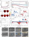
Electrochemical performance and stability of IEE system in SiMP half cells. a) Galvanostatic charge–discharge profiles of SiMP half cells with different systems. b) Long‐term cycling performance and corresponding CEs of Si electrode half cells in different systems at 0.5C (1C = 3.2 A g−1). c) TOF‐SIMS 3D reconstruction images for LiSi, PO2 , and C2HO . Differential capacity curves (dQ/dV versus V) of SiMP half cells in d) IEE and e) QSSE systems. f) Voltage gaps between the lithiation and delithiation peaks in differential capacity curves across the cycles. g) In situ galvanostatic EIS measurements of Si electrodes with different systems (in situ characterization). h) Cross‐sectional SEM images of Si electrodes in the pristine state, after the 1st cycle, and after the 30th cycle with different systems.
Figure 3
Figure 3
Characterization of Si electrodes half cells with different systems. a) Schematic illustration of a cell integrated with a force sensor and the components in the cell. Pressure changes and voltage profiles for b) IEE system and c) QSSE system. d) Galvanostatic charge–discharge voltage profiles and e) areal capacity retention of SiMP electrode half cells in IEE system with various areal mass loadings.
Figure 4
Figure 4
Electrochemical performance of SiMP||NCM811 full cell with IEE system. a) Galvanostatic charge–discharge profiles of the SiMP||NCM811 full cells with different systems. b) Capacity retention and corresponding CEs of the SiMP||NCM811 full cells with different systems at 0.2C (1C = 0.2 A g−1). c) Cycle performance of bi‐layer pouch‐type SiMP||NCM811 full cell with IEE system (Inset: Digital photo and cell configuration of a bi‐layer pouch‐type full cell). d) Comparison of the gravimetric and volumetric energy densities of the pouch‐type full cell in this work and previously reported using Si‐based anode full cells. e) Optical images for the LEDs powered by a bi‐layer pouch‐type full cell under various conditions, including flat, folded, cut once, and cut twice.
Figure 5
Figure 5
Post‐mortem analysis of NCM811 cathodes with IEE system. TOF‐SIMS 3D reconstruction images of certain species from NCM811 cathodes after 100 cycles of full cells with a) IEE and b) QSSE systems. XPS spectra of C 1s and F 1s of NCM811 cathodes from full cells with c) IEE and d) QSSE systems. Cross‐sectional SEM images of cathodes from full cells with e,f) IEE and g,h) QSSE systems.

References

    1. a) Ryu J., Song W. J., Lee S., Choi S., Park S., Adv. Funct. Mater. 2020, 30, 1902499;
    2. b) Cano Z. P., Banham D., Ye S. Y., Hintennach A., Lu J., Fowler M., Chen Z. W., Nat. Energy 2018, 3, 279.
    1. a) Wang Y., Cao G. Z., Adv. Mater. 2008, 20, 2251;
    2. b) Park C. M., Kim J. H., Kim H., Sohn H. J., Chem. Soc. Rev. 2010, 39, 3115. - PubMed
    1. a) Je M., Han D. Y., Ryu J., Park S., Acc. Chem. Res. 2023, 56, 2213; - PMC - PubMed
    2. b) Kang J., Han D. Y., Kim S., Ryu J., Park S., Adv. Mater. 2023, 35, 2203194; - PubMed
    3. c) Kim J., Lee H., Cha H., Yoon M., Park M., Cho J., Adv. Energy Mater. 2018, 8, 1702028.
    1. a) Janek J., Zeier W. G., Nat. Energy 2023, 8, 230;
    2. b) Janek J., Zeier W. G., Nat. Energy 2016, 1, 16141;
    3. c) Zhang L., Wang S., Wang Q., Shao H. Y., Jin Z., Adv. Mater. 2023, 35, 202303355; - PubMed
    4. d) Wang S., Zhang L., Zeng Q. H., Guan J. Z., Gao H. Q., Zhang L. Y., Zhong J., Lai W. Y., Wang Q., Adv. Energy Mater. 2024, 14, 202302876.
    1. a) Huo H. Y., Jiang M., Bai Y., Ahmed S., Volz K., Hartmann H., Henss A., Singh C. V., Raabe D., Janek J., Nat. Mater. 2024, 23, 543; - PMC - PubMed
    2. b) Cangaz S., Hippauf F., Reuter F. S., Doerfler S., Abendroth T., Althues H., Kaskel S., Adv. Energy Mater. 2020, 10, 2001320;
    3. c) Wang S., Xiao S. J., Li S. H., Liu C., Cai H. N., Sun W. Q., Huang Z. D., Lai W. Y., Angew. Chem., Int. Ed. 2024, 63, 202412434. - PubMed

LinkOut - more resources