

Freight wagon body design with increased load capacity
- PMID: 40240480
- PMCID: PMC12003748
- DOI: 10.1038/s41598-025-97152-7
Freight wagon body design with increased load capacity
Abstract
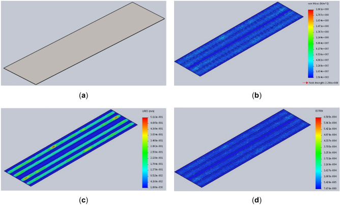
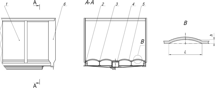
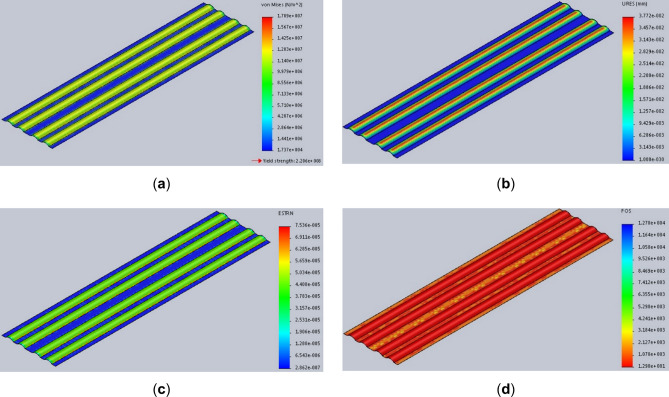
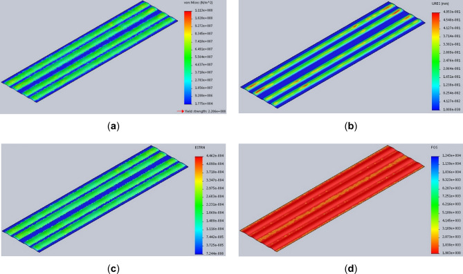
Increasing the load capacity of freight wagon bodies is a key issue aimed at improving the energy efficiency and competitiveness of rail transport. This study presents for the first time a design for a freight wagon body with increased load capacity and proposes new changes to the design of the freight wagon floor. To verify the proposed solution, CAD models of the freight wagon floor with thicknesses ranging from 3 to 6 mm were developed, and calculations were performed for von Mises stresses, resultant displacements, equivalent strains, and safety factors for each model. The factor of safety of the freight wagon floor structure has been increased by 5.2 times. The results indicated that the load capacity of the freight wagon with the modified floor increased by 1.6% to 2.7%, depending on the thickness, compared to the baseline floor construction with a thickness of 7 mm. In addition to effectively increasing the freight wagon's load, the proposed modifications maintain structural integrity and address mass considerations. Furthermore, these changes allow for the use of standard carbon steel, which provides additional economic benefits. The study confirms that the use of thinner materials in the floor construction can significantly enhance the overall performance of the freight wagon and operational efficiency in rail transport.
Keywords: Deformations; Design; Displacements; Freight wagon body; Load capacity; Stresses.
© 2025. The Author(s).
Conflict of interest statement
Declarations. Competing interests: The author declares no competing interests.
Figures


References
-
- Lingaitis, L.P., Mjamlin, S., Baranovsky, D., Jastremskas, V. Prediction methodology of durability of locomotives diesel engines, Eksploatacja i Niezawodnosc Maintenance and Reliability 2012, 14(2), 154–159.
-
- Lingaitis, L.P., Mjamlin, S., Baranovsky, D., Jastremskas, V. Experimental investigations on operational reliability of diesel locomotyves engines. Eksploatacja i Niezawodnosc Maintenance Reliability 2012, 14(1), 6–11.
-
- Chmielowiec, A. Algorithm for error-free determination of the variance of all contiguous subsequences and fixed-length contiguous subsequences for a sequence of industrial measurement data. Comput Stat36, 2813–2840 (2021).
-
- Baranovskyi, D., Myamlin, S., Podosonov, D. & Muradian, L. Determination of the filler concentration of the composite material to reduce the wear of the central bowl of the rail truck bolster. Ain Shams Eng. J.12, 102232. 10.1016/j.asej.2023.102232 (2023).
MeSH terms
LinkOut - more resources
Full Text Sources
Miscellaneous
