. 2025 Apr 22;122(16):e2423301122.
doi: 10.1073/pnas.2423301122. Epub 2025 Apr 17.

Exotic mechanical properties enabled by countersnapping instabilities

Affiliations

Exotic mechanical properties enabled by countersnapping instabilities

Paul Ducarme et al. Proc Natl Acad Sci U S A. .

Abstract

Mechanical snapping instabilities are leveraged by natural systems, metamaterials, and devices for rapid sensing, actuation, and shape changes, as well as to absorb impact. In all current forms of snapping, shapes deform in the same direction as the exerted forces, even though there is no physical law that dictates this. Here, we realize countersnapping mechanical structures that respond in the opposite way. In contrast to regular snapping, countersnapping manifests itself in a sudden shortening transition under increasing tension or a sudden increase in tensile force under increasing extension. We design these structures by combining basic flexible building blocks that leverage geometric nonlinearities. We demonstrate experimentally that countersnapping can be employed to obtain new exotic properties, such as unidirectional stick-slip motion, switchable stiffness that does not otherwise affect the state of the system, and passive resonance avoidance. Moreover, we demonstrate that combining multiple countersnapping elements allows sequential stiffness switching for elements coupled in parallel, or instantaneous collective switching for elements in series. By expanding the repertoire of realizable elastic instabilities, our work opens routes to principles for mechanical sensing, computation, and actuation.

Keywords: elastic instabilities; geometric nonlinearities; mechanical metamaterials; programmability; snapping.


Conflict of interest statement

Competing interests statement:The authors declare no competing interest.

Figures

Fig. 1.
Fig. 1.
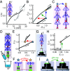
Combining nonlinear mechanical building blocks to realize countersnapping instabilities. Regular snapping instabilities observed in (A) a nonmonotonic force (F)–displacement (U) relation realized by a pair of springs forming a left buckled beam and driven from the connection point, and (B) a multivalued force–displacement relation achieved by serially coupling a nonmonotonic element to a spring. (C and D) Self-intersecting force–displacement relation that leads to countersnapping: (C) a sudden decrease in U when F is increased, or (D) a sudden increase in F when U is increased. (E and F) Realization of countersnapping elements with a network of three different weakly nonlinear springs (s1s3). (GI) Geometric construction of the force–displacement curves needed to achieve the countersnapping behavior. The color of the markers refer to the type of spring. Black markers refers to the global state. In (G and H), the dark gray rectangles represent the state before (G) and after (H) switching. The width and height of each rectangle are used to create the green marker which represents the state of spring s3. In (I), markers from both (G and H) are plotted together, which allows to draw the three local force–displacement curves. (JL) Experimentally evaluated nonlinear building blocks for a range of parameters. (J) Softening building block with a=[4,5,6] mm, b=[1.0,1.5,2.0] mm. (K) Stiffening building block with c=[12,13,14,15] mm. (L) Nonmonotonic building block with d=[5,7,9] mm, θ=[50°,60°,70°]. (M) Assembly of the building blocks that lead to countersnapping.
Fig. 2.
Fig. 2.
Experimental observation of countersnapping behavior. (A) Force–displacement curve for a countersnapping assembly obtained by increasing (dark gray) then decreasing (light gray) the applied displacement U and measuring the reaction force F. (B) Close-up on the critical point indicated in (A). The axes have been normalized U¯=U/Uc, F¯=F/Fc, where the subscript c indicates the critical point under controlled displacement. Uc'=25.2 mm, Fc'=0.88 N. Colored arrows indicate the jumps under controlled displacement (blue), controlled force (red), and mixed conditions (green). (C) Snapshots of the configuration just before (Left) and just after (Right) snapping during loading (displacement-controlled) (D) Setup for the force-controlled experiment: The structure is attached from the Top and a cup, suspended at the Bottom, is slowly filled with water. (E) Force–displacement curve obtained by increasing the applied force F and measuring the displacement U. The axes have been normalized U^=U/Uc', F^=F/Fc', where the subscript c’ indicates the critical point under controlled force. Uc'=23.9 mm, Fc'=0.81 N. (F) Snapshots just before (Left) and just after (Right) snapping. (G) Setup for loading under mixed conditions, measuring the elevation X2 of the weight. The structure is pulled upward from the Top by an increasing displacement X1 while the weight attached to the Bottom is initially sitting on a flat platform. (H) Weight elevation as a function of the applied displacement. The axes have been normalized X~1=X1/X1c'', X~2=X2/X1c'', where the subscript c” indicates the critical point under mixed conditions. X1c''=23.5 mm. (I) Snapshots just before (Left) and just after (Right) the sudden liftoff. Notice the higher weight elevation in the Right snapshot.
Fig. 3.
Fig. 3.
Experimental observation of unidirectional stick–slip behavior. (A and B) Sliding experiment setup used for the snapping (A) and countersnapping (B) structures. The block of foam is depicted by the gray rounded rectangles. (C and D) Change in distance between the contact point and the piece of foam over time, for the (C) snapping and (D) countersnapping structures. The gray star indicates the instant at which the countersnapping structure completely slides off the piece of foam. Each loading and unloading sequence lasts 9.38 s (±1.9%) in (C) and 16.87 s (±0.4%) in (D). (E) Snapshots of the sliding experiment using the countersnapping structure (side view) taken at fixed time intervals.
Fig. 4.
Fig. 4.
Experiments to demonstrate programmable and self-switching stiffness. (A) Close-up on the self-intersection of the force–displacement curve from Fig. 2A. (B) The two states, soft (0, blue) and stiff (1, yellow) that correspond to the intersection point in (A) have the same elongation under the same applied force, yet different stiffnesses. (C) Change in elongation ΔU over time during three episode of free oscillations. Each episode is triggered by a stimulus (slight pull and release) indicated by the whitened backgrounds. Between each episode, the state is manually switched by pulling or pushing on the weight, indicated by the darkened background. The red circles indicate the instant at which the state changes. The amplitude ΔU required to switch from 0 to 1 (resp. 1 to 0) is 5.0 mm (resp. −11.5 mm). (D) Experimental setup to for the free vibrations. (E) Close-up on the first two episodes of free oscillations highlighted by the boxes in (C). Each episode is triggered by a stimulus consisting of releasing the weight from a slightly stretched configuration compared to the intersection state, indicated by the red stars. The amplitude of that stretch is, respectively, 3.9 mm (Top) and 8.2 mm (Bottom). After releasing the weight when in state 0 (resp. state 1), the system oscillates freely at a frequency of 3.7 Hz (resp. 6.4 Hz). (F) Experimental setup for the forced vibrations. The sample is shaken vertically from the Top using a robotic arm (input), while the vertical position of the suspended weight is measured (output). (G) Evolution of the input and output displacements during forced vibrations, leading to resonance and a switch from soft to stiff (01, Top) and stiff to soft (10, Bottom). (H) Schematic representation of the resonance switches for the soft-to-stiff (01, Left) and stiff-to-soft (10, Bottom) transitions.
Fig. 5.
Fig. 5.
Experimentally observed collective behavior of countersnapping metamaterials. (A) Two parallel countersnapping elements controlled by displacement U. (B) Possible collective states of the system. (C) The binary state of the system (background color) as function of U, where bright (light) pink arrows indicate snapping events during loading (unloading). (D and E) Corresponding force–displacement curve (colors indicating state) and transition graph. (F) Snapshots of the {00}, {10} and {11} states at U = 22.3 mm near the intersection point of the force–displacement curves. (G) Close-up on the intersection point. (H) Two serially coupled countersnapping elements. (I) Possible collective states of the system. (J) State as function of U; note the avalanche transition {00}{11}, where both countersnapping elements flip simultaneously. (K and L) Corresponding force–displacement curve and transition graph. (M) Snapshots of the {00}, {10} and {11} states at U = 40.3 mm near the intersection point. (N) Close-up on the intersection point.
Fig. 6.
Fig. 6.
Avalanche transitions in serially coupled countersnapping elements. (A) Snapshots of two serially coupled countersnapping elements, steadily stretched under displacement control, before and after the sudden avalanche where both elements switch. (B) Snapshots of two countersnapping elements forming a chain whose total length is constant. Poking the Left element triggers a transition in both elements. Note that, despite the pair of countersnapping elements being oriented differently in panels (A and B), both arrangements correspond to the same (serial) coupling.

References

    1. Bertoldi K., Reis P. M., Willshaw S., Mullin T., Negative Poisson’s ratio behavior induced by an elastic instability. Adv. Mater. 22, 361–366 (2010). - PubMed
    1. Shan S., et al. , Multistable architected materials for trapping elastic strain energy. Adv. Mater. 27, 4296–4301 (2015). - PubMed
    1. Yang H., Ma L., Multi-stable mechanical metamaterials by elastic buckling instability. J. Mater. Sci. 54, 3509–3526 (2019).
    1. Wu L., Pasini D., In situ activation of snap-through instability in multi-response metamaterials through multistable topological transformation. Adv. Mater. 35, 2301109 (2023). - PubMed
    1. Raney J. R., et al. , Stable propagation of mechanical signals in soft media using stored elastic energy. Proc. Natl. Acad. Sci. U.S.A. 113, 9722–9727 (2016). - PMC - PubMed

LinkOut - more resources