. 2025 Apr 10:2025:7875699.
doi: 10.1155/vmi/7875699. eCollection 2025.

A Novel Dynamic Compression Angle-Stable Interlocking Intramedullary Nail: Description, Validation, and Model Evaluation

Affiliations

A Novel Dynamic Compression Angle-Stable Interlocking Intramedullary Nail: Description, Validation, and Model Evaluation

Luís Gustavo Gosuen Gonçalves Dias et al. Vet Med Int. .

Abstract

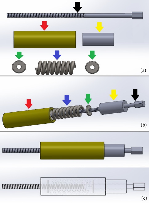
The stabilization of long-bone fractures using intramedullary nails offers significant biological advantages for bone healing. Nevertheless, the mechanical stability of the implant-bone interface remains suboptimal due to the absence of models capable of generating interfragmentary compression at the fracture site. To address these limitations, this study aims to describe and evaluate a novel dynamic compression angle-stable interlocking intramedullary nail (DCASIN), designed for use in conjunction with a compression device (CD). Its performance was compared with conventional and angle-stable interlocking intramedullary nails. Implantation was demonstrated using a tube-based bone model with transverse fractures. Compression was achieved in the proximal aspect of the DCASIN through an oblong hole that allowed the insertion of a Steinmann pin, which was then subjected to the thrust of the CD's primary screw (PS). To evaluate dynamic compression, a load cell connected to the Arduino/Genuíno Uno software was utilized. Three groups of interlocking nails were assessed: G1 (conventional), G2 (angle-stable), and G3 (DCASIN), with measurements taken at four time points (M1: prelocking, M2: after the first screw or PS for the DCASIN, M3: after the second implant, and M4: one-minute post-M3). No statistically significant differences in compression forces were observed for G1 and G2 across the measured time points. In contrast, G3 exhibited significantly higher compression at M2 than at M3 and M4, and its compression forces at M2, M3, and M4 were significantly greater than those in G1 and G2. Finite element analysis revealed no significant deformation in G3 during compression. In conclusion, the DCASIN combined with the CD achieved and sustained superior compression forces compared to conventional and angle-stable nails, thereby offering a promising alternative for the internal fixation of long bones.

Keywords: biological osteosynthesis; experimental implants; implants engineer; intramedullary fracture fixation; long bone fractures.


Conflict of interest statement

Luís Gustavo Gosuen Gonçalves Dias and São Paulo State University (UNESP) had patent #BR 10 2018 016021 4 licensed to the Brazilian National Institute of Industrial Property. The other authors declare no conflicts of interest.

Figures

Figure 1
Figure 1
Prototype illustration of the components of the compression device (CD) designed for dynamic compression when applied with the dynamic compression angle-stable interlocking intramedullary nail (DCASIN). (a) Components of the CD, with the primary screw (PS) (black arrow), spring retainer (red arrow), compression measurer (yellow arrow), washers (green arrow), and spring (blue arrow). (b) Sequential insertion of the components of the CD, starting with the compression measurer inserted into the PS, followed by the spring retainer housing a spring held by two washers. (c) Final apparatus and transparency vision of the CD.
Figure 2
Figure 2
Photographic illustration of the external implantation guide (EIG) components associated with CD. (a) EIG (red arrow), nail connector (NC) (green arrow), and nail connector fixator (pink arrow). (b) EIG and CD with primary screw (yellow arrow) and spring retainer (black arrow). (c, d) The NC is inserted in the EIG and fixed with the nail connector fixator. (e) The primary screw of CD is inserted through the cannulated hole of NC. (f) The tightening wrench (blue arrow) is used to thread the screw inside the novel DCASIN.
Figure 3
Figure 3
Prototype illustration of the body nail of the DCASIN, designed for dynamic compression when applied with the CD. (a, b) Frontal view with measurements in millimeters, depicting the oblong hole in the proximal portion of the nail (1), positioned between the two angle-stable holes. The distal portion (2) exhibits two angle-stable holes only. The threaded nail core (black arrow) originates from the proximal aspect of the nail and extends up to the oblong hole, facilitating the pushing of the implant (red arrow) inserted into the proximal aspect of the oblong hole. (c) The PS (yellow arrow) is inserted into the threaded nail core (black arrow) to make contact and push the Steinmann pin (red arrow), while the last hole of Portion 1 (purple arrow) is locked in an angle-stable position only after the PS is removed.
Figure 4
Figure 4
Prototype and photographic illustration for the modified test bench and synthetic specimens used for the assays for the dynamic compression of novel DCASIN and CD. (a) Prototype of the test bench, featuring two bench vises in the horizontal plane for specimen fixation and two others in the vertical plane for EIG fixation. (b) Test bench after the wood manufacturing. (c) Prototype of the specimens using PLA, with measures in millimeters and mimicking long cylindrical bones. (d) The final appearance of the modified test bench with the EIG, DCASIN, and CD. The distal specimen (green arrow) and the EIG (white arrow) were secured in the bench vises. The EIG was utilized with perforation guides (blue and black arrows) to insert angle-stable screws. An initial distance of 7 mm (pink arrow) was maintained between the proximal (yellow arrow) and distal specimens.
Figure 5
Figure 5
Sequential illustrative demonstration of the compression technique using the novel DCASIN and the CD. (a) The proximal specimen (yellow arrow) was free to axial motion, while the distal one was secured to the bench vise and fastened to the nail using two angle-stable screws (purple arrows). The PS was threaded along the nail core until it made contact with the Steinmann pin (red arrow), pushing it distally along the axial vector. This action led to the approximation of the distal specimen and resulted in compression of the initial gap (pink arrow). (b, c) The proximal specimen (yellow arrow) with a window to show the pathways. The red rectangle shows the site of implant insertion in the proximal position of the nail. The first (white arrow) and third (purple arrow) holes of the proximal portion were left unobstructed while the PS (black arrow) was inserted into the nail core. The sequence of figures in (d–i) demonstrates the anticipated displacement of the implant components during the execution of the compression technique. As the PS (black arrow) is threaded, the Steinmann pin (red arrow) is displaced distally into the oblong hole (green arrow).
Figure 6
Figure 6
Prototype illustration and representation of the technique adopted for the objective measurement of the compression technique for the DCASIN compared to CIN and ASIN. (a) Description of specimens used for PLA three-dimensional printing, featuring millimeter measurements and cylindrical bone shapes, adapted with perpendicular terminals for intimate contact with the beam-type strain gauge load cell. (b) Test bench setup with the ASIN model (red arrow), showing the specimen (yellow arrow) in contact with the load cell (white arrowhead) and NC (green arrow) with the EIG (white arrow). The load cell (white arrowhead) was secured to the test bench using a sinew and connected to the Arduino/Genuino Uno (yellow rectangle) via a cable (pink arrow). (c) Test bench setup with the DCASIN, highlighting the CD (blue arrow) and PS (orange arrow).
Figure 7
Figure 7
Graphical representation of finite element analysis execution, simulating the axial load exerted by the Steinmann pin on the bone specimen's orifice in both cortices. During the compression process, the primary screw applied axial pressure (red arrow), exerting force on the pin at two points on the distal surface of the cortical orifice (green arrow). A load of 26,000 g was applied, representing the maximum force value recorded during the compression test.
Figure 8
Figure 8
Sequential photographic representation of the interfragmentary compression achieved by the novel DCASIN. (a) Initially, the distal specimen (green arrow) was immobilized, while the proximal one (yellow arrow) remained free to axial motion. The positioning screw (PS) was advanced through the nail core to guide the Steinmann pin into the oblong hole (red arrow). (b–f) The sequential axial motion of the proximal specimen corresponding to the advancement of the PS. The distal displacement of the proximal specimen led to the complete closure of the initial 7-mm gap (pink arrow).
Figure 9
Figure 9
Graphical demonstrations of individual values corresponding to the compression force exerted by the CIN (G1) at different evaluation moments, captured by the Arduino/Genuino Uno computational platform, in the 10 specimens used.
Figure 10
Figure 10
Graphical demonstrations of individual values corresponding to the compression force exerted by the ASIN (G2) at different evaluation moments, captured by the Arduino/Genuino Uno computational platform, in the 10 specimens used.
Figure 11
Figure 11
Graphical demonstrations of individual values corresponding to the compression force exerted by the DCASIN (G3) at different evaluation moments, captured by the Arduino/Genuino Uno computational platform, in the 10 specimens used.
Figure 12
Figure 12
Finite element analysis results for the polylactic acid (PLA) specimen. (a) Definition of finite element mesh, with the distal portion of the specimen designated as the stable geometry, and green arrows representing the simulated contact surface, as observed during the compression technique. (b) Displacement under axial force of 26,000 g. (c) Equivalent deformation in the distal region of the orifice following the application of an axial force of 26,000 g.
Figure 13
Figure 13
Finite element analysis results for the natural adult cortical bone tissue specimen. (a) Definition of finite element mesh, with the distal portion of the specimen designated as the stable geometry, and green arrows representing the simulated contact surface, as observed during the compression technique. (b) Displacement under axial force of 26,000 g. (c) Equivalent deformation in the distal region of the orifice following the application of an axial force of 26,000 g.

Similar articles

References

    1. Johnston S. A., von Pfeil D. J. F., Déjardin L. M., Weh M., Roe S. Internal Fracture Fixation. In: Tobias K. M., Johnston S. A., editors. Veterinary Surgery: Small Animal . Saint Louis: Elsevier; 2017. pp. 1892–1983.
    1. Maritato K. C. A Brief History of Veterinary Locking Plates Applications. In: Barnhart M. D., Maritato K. C., editors. Locking Plates in Veterinary Orthopedics . Hoboken: Wiley-Blackwell; 2019. pp. 1–5.
    1. Ya’ish F. M. M., Nanu A. M., Cross A. T. Can DCP and LCP Plates Generate More Compression? The Effect of Multiple Eccentrically Placed Screws and Their Drill Positioning Guides. Injury . 2011;42(10):1095–1100. doi: 10.1016/j.injury.2011.02.012. - DOI - PubMed
    1. Augat P., von Rüden C. Evolution of Fracture Treatment With Bone Plates. Injury . 2018;49(Suppl 1):S2–S7. doi: 10.1016/S0020-1383(18)30294-8. - DOI - PubMed
    1. Déjardin L. M., Guiot L. P., von Pfeil D. J. Interlocking Nails and Minimally Invasive Osteosynthesis. Veterinary Clinics of North America: Small Animal Practice . 2012;42(5):935–962. doi: 10.1016/j.cvsm.2012.07.004. - DOI - PubMed

LinkOut - more resources