. 2025;10(4):448-459.
doi: 10.1038/s41560-025-01714-y. Epub 2025 Feb 13.

Direct air capture of CO2 for solar fuel production in flow

Affiliations

Direct air capture of CO2 for solar fuel production in flow

Sayan Kar et al. Nat Energy. 2025.

Abstract

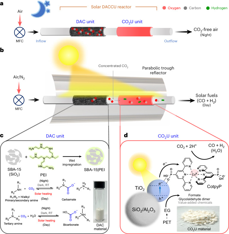
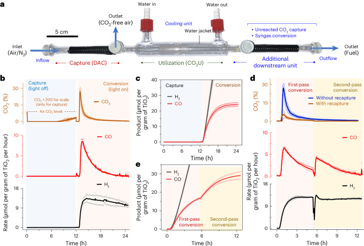
Direct air capture is an emerging technology to decrease atmospheric CO2 levels, but it is currently costly and the long-term consequences of CO2 storage are uncertain. An alternative approach is to utilize atmospheric CO2 on-site to produce value-added renewable fuels, but current CO2 utilization technologies predominantly require a concentrated CO2 feed or high temperature. Here we report a gas-phase dual-bed direct air carbon capture and utilization flow reactor that produces syngas (CO + H2) through on-site utilization of air-captured CO2 using light without requiring high temperature or pressure. The reactor consists of a bed of solid silica-amine adsorbent to capture aerobic CO2 and produce CO2-free air; concentrated light is used to release the captured CO2 and convert it to syngas over a bed of a silica/alumina-titania-cobalt bis(terpyridine) molecular-semiconductor photocatalyst. We use the oxidation of depolymerized poly(ethylene terephthalate) plastics as the counter-reaction. We envision this technology to operate in a diurnal fashion where CO2 is captured during night-time and converted to syngas under concentrated sunlight during the day.

Keywords: Carbon capture and storage; Photocatalysis; Solar fuels.


Conflict of interest statement

Competing interestsA patent application covering integrated direct air capture and utilization into solar fuels has been submitted on behalf of the University of Cambridge via its technology transfer office, Cambridge Enterprise with co-inventors S. Kar and E.R. (application no. GB2408950.0). The other authors declare no competing interests.

Figures

Fig. 1
Fig. 1. DACCU through a dual-bed flow reactor consisting of DAC and CO2U units.
a, Schematics of the system during light-off night operation. b, Schematics of the overall system during light-on day operation. c, The carbon capture unit with chemical CO2 capture and release equations. d, The solar-driven CO2U unit material composition and the relevant reduction and oxidation reactions. RT, room temperature; MFC, mass flow controller; PEI, polyethyleneimine; PET, poly(ethylene terephthalate); EG, ethylene glycol.
Fig. 2
Fig. 2. DAC and solar-driven photothermal release of CO2.
a, CO2 levels in the outflow during DAC and the adsorbed CO2 amount over time. DAC was performed with 600 mg of SBA-15|PEI adsorbent with an airflow rate of 90 ml min–1 at room temperature. b, Photothermal CO2 desorption setup with photothermal coating and parabolic trough reflector (note that the light source is for demonstration purposes only and different from the actual solar simulator used). c, CO2 concentration in outflow gas stream during release with different flow rates under 3 suns of solar irradiation with photothermal cover. In all cases, the adsorbent bed temperatures reached around 85–100 °C across different regions under concentrated light during desorption. For a, data are presented as the average of two independent runs and the individual data points are shown in hollow circles. Source data
Fig. 3
Fig. 3. Characterization and performance of the CO2U unit.
a, HAADF-STEM image and the relevant EDS maps (O, Si, Ti, N) of the composite. b, The effect of different alcohol electron donors on H2 and CO formation. Reactions were carried out in batch with 100 mg of CO2U composite (nSiO2|TiO2|CotpyP) and 0.15 ml of electron donor under 1 sun (100 mW cm–2, AM 1.5G) for 20 h. c, The effect of N2 versus CO2 carrier gas on product formation in fixed-bed flow setup. Reactions were performed with 250 mg of CO2U composite, moistened with 0.50 ml EG, under 1-sun illumination at a carrier gas flow rate of 1 ml min−1. d, The effect of different support materials on performance under similar conditions. e, An image of the parabolic trough reflector used for light concentration with the mounted tubular fixed-bed reactor. f, The effect of increasing solar intensity (around 3 suns) via reflector on CO formation when using γ-Al2O3|TiO2|CotpyP as the CO2U composite. g, The effect of temperature regulation on CO and H2 formation. The 43 oC and 56 oC reactions were performed without temperature regulation (elevated temperatures due to solar thermal heating), whereas in the 25 oC reaction, temperature was kept steady using a water jacket. h, Product evolution with time under 3-sun illumination when temperature was kept steady at 25 °C. For bd and fh, data are presented as the average of two independent runs and the individual data points are shown in hollow circles. Source data
Fig. 4
Fig. 4. CO2U oxidation product analysis and dilute CO2 response.
a, The overall reduction and oxidation products observed (γ-Al2O3|TiO2|CotpyP as CO2U composite and EG as electron donor, reaction time 12 h). b, Total charge carriers involved in product formation. c, Long-term product formation activities and CO selectivity when PET-derived EG was used as reductant (for the EG derivation protocol from PET, see Methods). Reaction was performed at a CO2 flow rate of 3 ml min−1. d, The effect of CO2 dilution on CO generation in different carrier gases (CO2 in nitrogen, air). All reactions were performed under 3-sun illumination at 25 oC temperature. For a, b and d, data are presented as the average of two independent runs and the individual data points are shown in hollow circles. Source data
Fig. 5
Fig. 5. DACCU to produce solar syngas.
a, The designed reactor for in-flow DAC and CO2U. b, CO2 levels and photocatalytic CO and H2 formation rates in the outflow during DACCU. The CO2 values during capture (0–12 h) are multiplied by a factor of 200 for ease of visualization. DAC was performed during light-off operation at room temperature under airflow (90 ml min−1) and the CO2U is carried out during light-on operation under 3-sun illumination at 25 oC under N2 flow (1 ml min−1). c, Cumulative H2 and CO yield over time during DACCU. d, Recapture and rerouting of unreacted CO2 for increased conversion and low carbon emission. The additional downstream unit was loaded with fresh adsorbents for unreacted CO2 capture and rerouting during conversion. e, Cumulative H2 and CO formation over time during first- and second-pass conversion during operation under simulated solar irradiation. Data are presented as the average of two independent runs, and the individual data points are shown in hollow circles. Source data

Similar articles

Cited by

References

    1. Sanz-Pérez, E. S., Murdock, C. R., Didas, S. A. & Jones, C. W. Direct capture of CO2 from ambient air. Chem. Rev.116, 11840–11876 (2016). - PubMed
    1. McQueen, N. et al. A review of direct air capture (DAC): scaling up commercial technologies and innovating for the future. Prog. Energy3, 032001 (2021).
    1. Erans, M. et al. Direct air capture: process technology, techno-economic and socio-political challenges. Energy Environ. Sci.15, 1360–1405 (2022).
    1. Chauvy, R. & Dubois, L. Life cycle and techno-economic assessments of direct air capture processes: an integrated review. Int. J. Energy Res.46, 10320–10344 (2022).
    1. Bui, M. et al. Carbon capture and storage (CCS): the way forward. Energy Environ. Sci.11, 1062–1176 (2018).

LinkOut - more resources