Review
. 2025 Apr 25;104(17):e42265.
doi: 10.1097/MD.0000000000042265.

Current status and prospects of endovascular treatment for intracranial vertebral artery aneurysms: A narrative review

Affiliations
Review

Current status and prospects of endovascular treatment for intracranial vertebral artery aneurysms: A narrative review

Yanming Qu et al. Medicine (Baltimore). .

Abstract

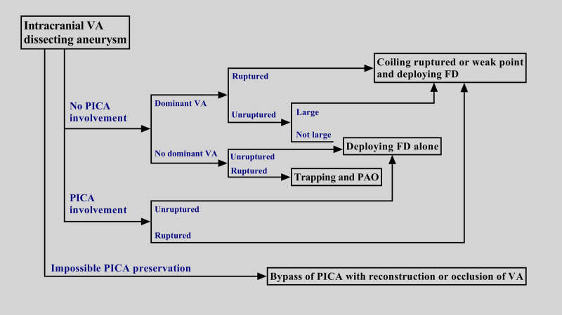
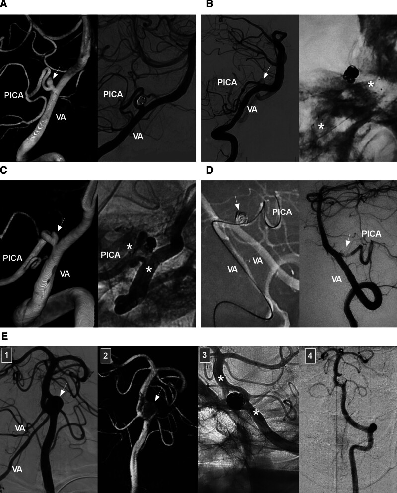
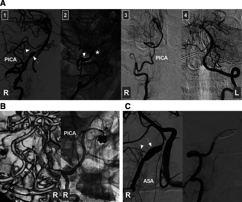
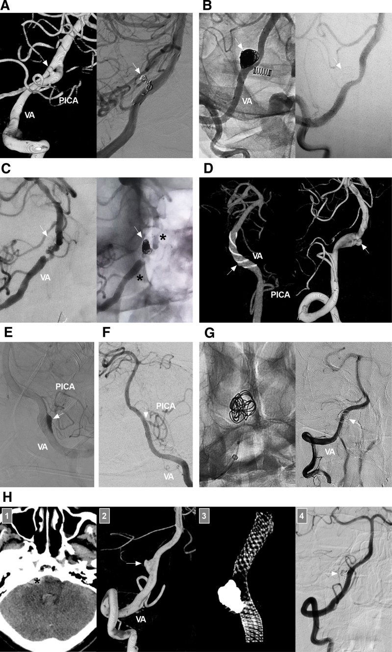
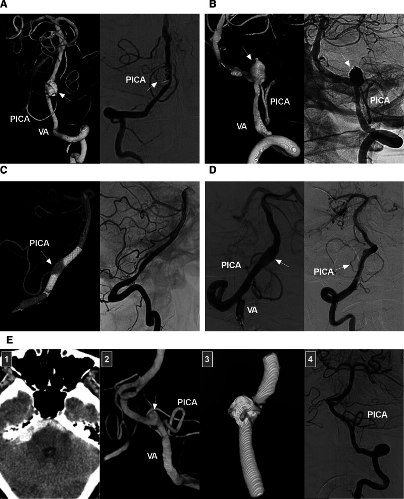
Intracranial vertebral artery (VA) aneurysms are complex entities. Endovascular treatment (EVT) can be used to treat intracranial VA aneurysms. Nevertheless, managing these lesions with EVT remains challenging. Moreover, the suitability of EVT for every type of intracranial VA aneurysm has not been fully confirmed. Therefore, we conducted a needed review of the current literature and our experience summarizing the current status of and advancements in EVT in the management of intracranial VA aneurysms. In our review, several issues are discussed, including the anatomy and anomalies of the intracranial VA, the classification and natural history of intracranial VA aneurysms, indications and techniques for EVT in the management of intracranial VA aneurysms, and the outcomes of and complications experienced by patients who undergo EVT. A flowchart describing EVT options for dissecting intracranial VA aneurysms derived from the findings of this review and our experience is provided. The key to successful EVT is preservation of the posterior inferior cerebellar artery and avoidance of injury to any brainstem perforators. Currently, intracranial VA reconstruction via flow diverter deployment plays an important role in achieving successful treatment. For appropriate cases, both reconstructive and deconstructive EVT can result in good patient outcomes. However, EVT-related complications should be considered. If management of complex intracranial VA aneurysms with EVT would be expected to disproportionally harm the patient, extracranial-intracranial bypass and aneurysmectomy are often necessary. In addition, new products and techniques that show promise for achieving successful EVT in the management of intracranial VA aneurysms are described.

Keywords: aneurysm; endovascular treatment; intracranial vertebral artery; prognosis; review.


Conflict of interest statement

The authors have no funding and conflicts of interest to disclose.

Figures

Figure 1.
Figure 1.
Flow chart of the literature search.
Figure 2.
Figure 2.
Intracranial VA anatomy and anomalies. (A) PICA anatomy: panel 1: DSA image showing the PICA and AICA sharing a common trunk (arrow); panel 2: DSA image showing the PICA (arrow) emerging from the distal VA; panel 3: DSA image showing the PICA (arrow) emerging from the intracranial proximal VA; panel 4: DSA image showing the PICA (arrow) emerging from the extracranial VA. (B) ASA and PSA anatomy: panel 1: DSA image showing the ASA (arrow) emerging from the VA; panel 2: DSA image showing the PSA (arrow) emerging from the VA; panel 3: DSA image showing the ASA and PSA (arrows) emerging from the VA; panel 4: DSA image showing a perforating artery (arrow) emerging from the VA. (C) VA anomaly: left panel: DSA image showing 2 fenestrations (asterisks) of the VA; middle panel: DSA image showing a VA terminating at the PICA; right panel: CTA image showing a VA emerging from the primitive hypoglossal artery (arrow). (D) CTA showing VA dolichoectasia, a form of vertebrobasilar dolichoectasia. AICA = anterior inferior cerebellar artery, ASA = anterior spinal artery, BA = basilar artery, CTA = computed tomography angiography, DSA = digital subtraction angiography, PICA = posterior inferior cerebellar artery, PSA = posterior spinal artery, VA = vertebral artery.
Figure 3.
Figure 3.
Types of intracranial VA aneurysms. (A) DSA images showing a saccular aneurysm (arrow) at the PICA-VA junction (left panel), a saccular aneurysm (arrow) in a fenestration at the VA terminus (middle panel), and a dissecting aneurysm (arrow) of the intracranial VA trunk (right panel). (B) DSA images showing a pre-PICA (below the PICA) VA trunk aneurysm (arrow) (left panel), a VA trunk aneurysm (arrow) with PICA involvement (middle panel), and a post-PICA (above the PICA) VA trunk aneurysm (arrow) (right panel). DSA = digital subtraction angiography, PICA = posterior inferior cerebellar artery, VA = vertebral artery.
Figure 4.
Figure 4.
Flowchart for selecting the method of endovascular treatment for intracranial VA dissecting aneurysms. FD = flow diverter, PAO = parent artery occlusion, PICA = posterior inferior cerebellar artery, VA = vertebral artery.
Figure 5.
Figure 5.
Endovascular treatment of aneurysms at the VA-PICA junction. (A) Coiling alone: left panel: DSA image showing an aneurysm (arrow) at the VA-PICA junction; right panel: follow-up DSA image showing complete occlusion of the aneurysm. (B) Stent-assisted coiling: left panel: DSA image showing a coiled saccular aneurysm (arrow) at the VA-PICA junction; right panel: X-ray image showing a stent (asterisks) deployed in the VA to cover the origin of the PICA. (C) Coiling assisted by antegrade stenting from the VA to the PICA: DSA image showing an aneurysm (arrow) at the VA-PICA junction; right panel: Unsubtracted DSA image showing coiling of the aneurysm via stenting (asterisks) from the ipsilateral VA to the PICA. (D) Coiling assisted by retrograde stenting from the contralateral VA to the PICA: Roadmap image showing a recurrently coiled saccular aneurysm (arrow) at the VA-PICA junction; the PICA was catheterized from the contralateral VA to await delivery of the stent; right panel: DSA image showing the coiled aneurysm (arrow). (E) panels 1 and 2: DSA and its reconstructive images showing a saccular aneurysm (arrows) in a VA fenestration; panel 3: DSA image showing coiling of the aneurysm with stenting assistance (asterisks); panel 4: follow-up DSA image showing complete occlusion of the aneurysm. DSA = digital subtraction angiography, PICA = posterior inferior cerebellar artery, VA = vertebral artery.
Figure 6.
Figure 6.
Deconstructive treatment for intracranial VA dissecting aneurysms without PICA involvement. (A) Proximal VA PAO: panel 1: DSA image showing a right VA dissecting aneurysm (arrow) and a perforating artery (arrowhead) emerging from the aneurysm; panel 2: Unsubtracted DSA image showing that the aneurysm (asterisk) is packed loosely and the proximal VA (arrowhead) is densely coiled; panels 3 and 4: 6-month follow-up DSA images of the bilateral VAs showing that the aneurysm has been cured, the right VA is supplying only the PICA, and the left VA is supplying the BA. The patient did not experience new neurologic deficits during and after treatment. (B) Trapping plus PAO: left panel: Computed tomography angiography showing a right VA dissecting aneurysm (arrow); right panel: DSA image showing trapping of the aneurysm and occlusion of the proximal VA (arrowhead). (C) Trapping with ischemia symptoms: left panel: DSA image showing a right VA dissecting aneurysm (arrow), a perforating artery (arrowhead) emerging from the aneurysm, and the ASA emerging from the end of the aneurysm; right panel, DSA image showing coiling of the aneurysm and occlusion of the perforating artery and ASA; postoperatively, the patient experienced symptoms of brainstem ischemia and recovered gradually but incompletely. ASA = anterior spinal artery, DSA = digital subtraction angiography, L = left, PAO = parent artery occlusion, PICA = posterior inferior cerebellar artery, R = right, VA = vertebral artery.
Figure 7.
Figure 7.
Reconstructive treatment for intracranial VA dissecting aneurysms without PICA involvement. (A) Traditional stent-assisted coiling: left panel: DSA image showing a small dissecting aneurysm of the VA post-PICA (arrow); right panel: DSA image showing coiling of the aneurysm (arrow) with stenting assistance. (B) Traditional stent-assisted coiling: left panel: unsubtracted DSA image showing a large VA dissecting aneurysm (arrow) that has been coiled with stenting assistance; right panel: follow-up DSA image showing cure of the aneurysm (arrow). (C) Neuroform Atlas stent-assisted coiling: left panel: DSA image showing a VA dissecting aneurysm (arrow) that has been coiled with stenting assistance; the parent VA has multiple tandem stenoses; right panel: unsubtracted DSA image showing the coiling (arrow) and stent markers (asterisks). (D) Recurrent VA dissecting aneurysm: left panel: reconstructive DSA image showing a VA dissecting aneurysm (arrow) covered by a LEO stent; right panel: follow-up DSA image showing aneurysm (arrow) recurrence. (E) FD deployment alone: DSA image showing contrast agent retention (arrow) in the aneurysm after FD deployment. (F) DSA image showing a narrowed PICA at the origin (arrow) after FD deployment. (G) FD deployment with loose coiling: left panel: X-ray image showing a VA dissecting aneurysm treated by FD deployment with loose coiling; right panel, follow-up DSA image showing cure of the aneurysm (arrow). (H) Ruptured aneurysm treated with FD deployment and coiling: panel 1: computed tomography image showing subarachnoid hemorrhage (asterisk); Panel 2: DSA image showing a VA aneurysm (arrow); Panel 3: vaso-reconstructive image showing the FD and coil; panel 4: follow-up DSA image showing that the aneurysm (arrow) has been cured. DSA = digital subtraction angiography, FD = flow diverter, PICA = posterior inferior cerebellar artery, VA = vertebral artery.
Figure 8.
Figure 8.
Reconstructive treatment for VA dissecting aneurysms with PICA involvement. (A) Traditional stent-assisted coiling: follow-up 3-dimensional (left panel) and 2-dimensional (right panel) DSA images showing complete occlusion of a sidewall VA trunk dissecting aneurysm (arrow) with PICA involvement; the PICA has been preserved. (B) Traditional stent-assisted coiling: left panel: 3-dimensional DSA image showing a saccular VA trunk aneurysm (arrow) with PICA involvement; right panel: unsubtracted DSA image showing that the aneurysm (arrow) has been coiled with stenting assistance; the PICA has been preserved. (C) FD deployment alone: left panel: reconstructive DSA image showing coverage of the aneurysm (arrow) by an FD; the PICA is patent; right panel: 1-year follow-up DSA image showing cure of the dissecting aneurysm and preservation of the PICA. (D) FD deployment alone: left panel: DSA image showing a VA dissecting aneurysm (arrow) following FD coverage; the PICA (arrow) is patent; right panel: 6-month follow-up DSA image showing reconstruction of the VA, regression of the aneurysm (arrow), and patency and thinning of the PICA. (E) FD deployment with adjunctive coiling: panel 1: Computed tomography image showing subarachnoid hemorrhage (asterisk); panel 2: 3-dimensional DSA image showing a VA dissecting aneurysm (arrow), with the PICA (arrowhead) emerging from the proximal portion of the aneurysm; Panel 3: Image showing the FD device and coils; Panel 4: 6-month follow-up DSA image showing cure of the aneurysm and patency of the PICA. DSA = digital subtraction angiography, FD = deployment, PICA = posterior inferior cerebellar artery, VA = vertebral artery.
Figure 9.
Figure 9.
EVT of bilateral intracranial VA dissecting aneurysms. (A) FD deployment for bilateral VA dissecting aneurysms: panels 1 and 2: vaso-reconstructive DSA images showing 2 VA aneurysms treated with FD deployment; panel 3 and 4: 1-year follow-up DSA image showing cure of the left but not the right aneurysm. (B) PAO for ipsilateral ruptured VA dissecting aneurysms: panel 1: computed tomography angiography image showing bilateral VA dissecting aneurysms; panel 2: DSA image showing a right VA dissecting aneurysm (arrow) at the PICA origin; panel 3: Unsubtracted DSA image showing loose coiling of the right aneurysm (asterisk) and complete occlusion of the proximal VA (arrowhead); panel 4: DSA image showing a right PICA supplied retrogradely by the left VA; plans were made to treat the left aneurysm (arrow) later. (C) Simultaneous deconstructive and reconstructive EVT: panel 1: reconstructive 3-dimensional DSA image showing bilateral VA dissecting aneurysms, the left of which recurred after coiling assisted by traditional stenting, while the left PICA has a double origin (Arrows with numbers 1 and 2); panel 2: microcatheter angiography in the lower origin of the PICA (arrow with number 1) showing the course of the vessel; panel 3: vaso-reconstructive DSA image showing coil occlusion of the left aneurysm (asterisk) and FD deployment to cover the right aneurysm; panel 4: 6-month follow-up DSA image of the right VA showing cure of the right aneurysm and sufficient blood flow to the vertebrobasilar arteries from the right VA. DSA = digital subtraction angiography, EVT = endovascular treatment, FD = flow diverter, L = left, PAO = parent artery occlusion, PICA = posterior inferior cerebellar artery, R = right, VA = vertebral artery.
Figure 10.
Figure 10.
Complications of traditional coiling EVT. (A) Hemorrhagic complications: left panel, DSA image showing an aneurysm at the VA and PICA junction that ruptured during coiling and contrast agent extravasation (arrow); right panel: follow-up DSA image showing complete aneurysm occlusion (arrow). (B) Hemorrhagic complications: left panel: DSA image showing a VA dissecting aneurysm perforated by the microcatheter and a coil loop (arrowhead). right panel: DSA image showing complete coiling of the aneurysm (arrow). (C) Ischemic complications: panel 1: DSA image showing coiling of an aneurysm (arrow) with PICA involvement; panel 2: Unsubtracted DSA image showing occlusion of the VA (arrowhead) proximal to an aneurysm; panel 3: DSA of a contralateral VA showing irrigation of the PICA on the side of the aneurysm by retrograde blood flow; panel 4: postoperative magnetic resonance diffuse sequence image showing acute infarction of the PICA territory. (D) Mild brainstem compression due to a mass effect: left panel: unsubtracted DSA image showing a large VA aneurysm treated by aneurysm trapping (arrow) and proximal PAO (arrowhead); right panel: postoperatively, a patient who experienced hemiplegia shows no hemorrhage on CT imaging. 1 week later, the patient had recovered. (E) Severe brainstem compression due to a mass effect: unsubtracted DSA image showing a large VA aneurysm (arrow) treated by proximal PAO (arrowhead); right panel: 1 day after EVT, the patient experienced respiratory arrest; CT image shows a highly dense aneurysm with a mass effect due to thrombosis (frame); 3 days later, the patient died. CT = computed tomography, DSA = digital subtraction angiography, EVT = endovascular treatment, PAO = parent artery occlusion, PICA = posterior inferior cerebellar artery, VA = vertebral artery.
Figure 11.
Figure 11.
Complications of FD deployment. (A) VA occlusion after FD deployment: panel 1: DSA image of the left VA showing a coiled VA aneurysm (arrow) covered by an FD; panel 2: 6-month follow-up DSA image of the right VA showing that the vessel supplies the vertebrobasilar arteries; panel 3: DSA image of the left VA showing that the vessel terminates at the PICA and that the VA distal to the PICA is occluded (left panel); Reconstructive DSA image showing the FD device (arrows) and coils in the occluded left VA (right panel). (B) Hemorrhagic complications: left panel: vaso-reconstructive DSA image showing a VA dissecting aneurysm (arrow) treated with FD deployment; right panel: 6 h after EVT, computed tomography imaging shows subarachnoid hemorrhage (frame), indicating aneurysm rupture. (C) VA aneurysm with a mass effect after FD deployment: left panel: DSA image showing a large intracranial VA aneurysm (arrow); right panel: vaso-reconstructive DSA image showing FD coverage of the aneurysm (arrow). Postoperatively, the patient experienced weakness in the left upper and lower limbs, while MRI showed no hemorrhage or infarction. Three days later, the patient recovered, indicating that the aneurysm had expanded after FD deployment. (D) VA aneurysm with mass effect after FD deployment: panel 1: MRI showing a lesion (arrow) with a mass effect to the brainstem; panel 2: vaso-reconstructive DSA image showing the aneurysm (arrow) covered by the FD. panel 3: 6-month follow-up DSA image showing complete aneurysm occlusion; panel 4: follow-up MRI showing that the aneurysm (arrow) has not shrunk. DSA = digital subtraction angiography, MRI = magnetic resonance image, PICA = posterior inferior cerebellar artery, VA = vertebral artery.
Figure 12.
Figure 12.
Combined EVT and aneurysmectomy in treating a giant intracranial VA aneurysm. (A) Enhanced magnetic resonance (left panel) and CT (right panel) images showing a lesion with a mass effect in the posterior fossa. (B) CT image showing the area of interest after exploratory craniotomy. (C) CT angiography image confirming that the lesion is an aneurysm. (D) Panel 1: Roadmap image showing the rupture point (arrow) of a giant VA aneurysm; panel 2: DSA image of the right VA showing occlusion of the aneurysm and parent VA with coils; panel 3: DSA image of the left VA showing that the vessel supplies the right VA distal to the aneurysm and basilar artery. (D) Postoperative CT showing the results of aneurysmectomy and resolution of the mass effect. CT = computed tomography, DSA = digital subtraction angiography, L = left, R = right, VA = vertebral artery.

Similar articles

References

    1. Lehto H, Niemelä M, Kivisaari R, et al. . Intracranial vertebral artery aneurysms: clinical features and outcome of 190 patients. World Neurosurg. 2015;84:380–9. - PubMed
    1. Durongwatana N, Sriamornrattanakul K, Wongsuriyanan S, Akharathammachote N. Microsurgical treatment of vertebral artery dissection: surgical strategies and treatment outcomes. World Neurosurg. 2022;159:e375–88. - PubMed
    1. Lv X, Lv M, Li Y, Yang X, Jiang C, Wu Z. Endovascular treatment of ruptured and unruptured vertebral artery aneurysms. Neuroradiol J. 2011;24:677–86. - PubMed
    1. Hernández-Durán S, Ogilvy CS. Clinical outcomes of patients with vertebral artery dissection treated endovascularly: a meta-analysis. Neurosurg Rev. 2014;37:569–77. - PubMed
    1. Guo Y, Song Y, Hou K, Yu J. Intracranial fusiform and circumferential aneurysms of the main trunk: therapeutic dilemmas and prospects. Front Neurol. 2021;12:679134. - PMC - PubMed

MeSH terms