. 2025 Jul;12(25):e2501148.
doi: 10.1002/advs.202501148. Epub 2025 Apr 29.

Suspended Tissue Open Microfluidic Patterning (STOMP)

Affiliations

Suspended Tissue Open Microfluidic Patterning (STOMP)

Amanda J Haack et al. Adv Sci (Weinh). 2025 Jul.

Abstract

Free-standing tissue structures tethered between pillars are powerful mechanobiology tools for studying cell contraction. To model interfaces ubiquitous in natural tissues and upgrade existing single-region suspended constructs, we developed Suspended Tissue Open Microfluidic Patterning (STOMP), a method to create multi-regional suspended tissues. STOMP uses open microfluidics and capillary pinning to pattern subregions within free-standing tissues, facilitating the study of complex tissue interfaces, such as diseased-healthy boundaries (e.g., fibrotic-healthy) and tissue-type interfaces (e.g., bone-ligament). We observed altered contractile dynamics in fibrotic-healthy engineered heart tissues compared to single-region tissues and differing contractility in bone-ligament enthesis constructs compared to single-tissue periodontal ligament models. STOMP is a versatile platform - surface tension-driven patterning removes material requirements common with other patterning methods (e.g., shear-thinning, photopolymerizable) allowing tissue generation in multiple geometries with native extracellular matrices and advanced four-dimensional (4D) materials. STOMP combines the contractile functionality of suspended tissues with precise patterning, enabling dynamic and spatially controlled studies.

Keywords: hydrogel patterning; open microfluidics; suspended tissue; tissue engineering.


Conflict of interest statement

Multiple authors have filed patent 18/669,367 and 63/665,194 through the University of Washington on STOMP and related technology. ABT reports filing multiple patents through the University of Washington and receiving a gift to support research from Ionis Pharmaceuticals. EB and ABT have ownership in Seabright, LLC, which will advance new tools for diagnostics and clinical research. EB has ownership in Salus Discovery, LLC, and Tasso, Inc. and is employed by Tasso, Inc., Seabright, LLC, and the University of Washington. NJS has ownership in Stasys Medical Corporation, Inc. and has ownership and is a scientific advisor in Curi Bio, Inc. Technologies from Seabright, LLC, Salus Discovery, LLC, Tasso, Inc., Stasys Medical Corporation, Inc., and Curi Bio, Inc. are not included in this publication. EB is an inventor on multiple patents filed by Tasso, Inc., the University of Washington, and the University of Wisconsin Madison. The terms of this arrangement have been reviewed and approved by the University of Washington in accordance with its policies governing outside work and financial conflicts of interest in research. All other authors declare they have no competing interests.

Figures

Figure 1
Figure 1
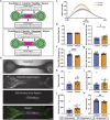
Workflow of generating single and multi‐region suspended tissues using the STOMP platform. a) Image of the STOMP platform, which includes a removable patterning device containing an open channel that interfaces with a pair of vertical posts. The patterning device is held in place to the base of the posts with holding clips. b) Schematic of the STOMP platform. A cell‐laden hydrogel is pipetted into the open channel, where it flows via surface‐tension driven forces across the open channel and anchors onto the suspended posts, thus generating a free‐standing suspended tissue. c) Side view of the resulting suspended tissue cultured in a 24‐well plate. d) Workflow of patterning a tissue composed of a single region, where the composition is the same across the tissue. e) Top‐down view of the capillary pinning features along the open channel that are used to pin the fluid front. f) Fluorescent image of patterned 3T3 mouse fibroblast cells laden in a fibrin hydrogel using STOMP. The outer region of 3T3 cells was dyed by CellTracker Green (green) and was pipetted first. The middle region of 3T3 cells was dyed by CellTracker Red (magenta). Scale bar is 500 µm. g) Workflow of patterning tissues comprising three distinct regions. Corresponding video stills show patterning of purple‐colored agarose in the outer regions first, followed by patterning yellow‐colored agarose in the middle region. Full video can be seen in Movie S1 (Supporting Information). All scale bars are 2 mm. h) Side view image of multi‐region agarose suspended hydrogel construct. Scale bar is 2 mm.
Figure 2
Figure 2
Characterization of capillary pinning features used in STOMP to generate multi‐region suspended tissues. Geometric considerations of a) vampire and b) cavity pinning feature designs. Graphs of maximum Laplace pinning pressure plotted against c) α, pin angle of the vampire feature, and d) β, pin angle of the cavity feature. Solid lines represent a Laplace pinning pressure (ΔPvampire or ΔPcavity) for a contact angle of θ = 30°, which is the average contact angle for 5 mg mL−1 collagen on 3D‐printed resin treated with 1% BSA at room temperature for 1 h. Upper and lower bounds of the Laplace pinning pressure is calculated based on the largest measured contact angle (θ = 48°) and the smallest measured contact angle (θ = 15°) on 1% BSA‐treated 3D‐printed resin. If the Laplace pinning pressure is greater than that of the hydrostatic pressure (ΔPhydrostatic = 33.5 Pa) then pinning is predicted to occur (shaded in green). If the Laplace pinning pressure is less than ΔPhydrostatic, then pinning will not occur (shaded in magenta). e) Representative video still images of 23 µL of a 5 mg mL−1 precursor collagen solution pipetted into two different 1% BSA treated STOMP devices containing the vampire pinning features; left four images use devices with α = 20° and right four images use devices α = 45°. f) Representative video still images of 23 µL of a 5 mg mL−1 precursor collagen solution pipetted into two different 1% BSA treated STOMP devices containing the cavity pinning features; left four images uses devices with β = 40° and right four images use devices with β = 100°. Scale bars on insets are 1 mm. All other scale bars are 3 mm. g) Visualization for the loss of pinning mechanism, where a pink arrow indicates the direction of flow of the purple hydrogel, with pinning first lost at the bottom of the channel.
Figure 3
Figure 3
Patterned engineered heart tissues (EHTs). a) Conditions tested for modeling a fibrotic region in an EHT using STOMP, where the middle region has a higher fibrin content and lower cardiomyocyte density than the regions at either end. b) Representative brightfield and fluorescent images of a control EHT seeded with HS5‐GFP human bone marrow stromal cells (green) on the two outer regions near the flexible and rigid posts, and HS5‐mCherry cells (magenta) in the center region. All scale bars are 500 µm. Full video of an unpaced EHT beating can be seen in Movie S6 (GFP channel) and Movie S7 (mCherry channel). c) Average twitch force traces of patterned control and fibrotic EHTs under 1.5 Hz pacing. d) Paced beat rate of patterned control and fibrotic EHTs. e) Spontaneous unpaced beat rate of patterned control and fibrotic EHTs. While all EHTs developed effective electromechanical coupling and were able to follow a pacing frequency of 1.5 Hz, fibrotic EHTs showed an elevated spontaneous beat rate when pacing was not applied. Diastolic function of control and fibrotic EHTs under 1.5 Hz pacing for f) time to 50% relaxation and g) time to 90% relaxation. Fibrotic EHTs show a delay in time to 50% relaxation and no change in the time to 90% relaxation. Systolic function of control and fibrotic EHTs under 1.5 Hz pacing, where fibrotic EHTs showed no differences in h) maximum twitch force, i) specific force, or j) shortening velocity, but they did have a reduced (k) time to peak as compared to controls. Each shape (triangle, circle, square) represents an independent experiment for control EHTs (n = 12) and fibrotic EHTs (n = 14). Each data point is a separate tissue, with lines representing mean ± SEM. Statistical analysis was performed using unpaired t‐test with two tails. *p ≤ 0.05, **p ≤ 0.01, ****p ≤ 0.0001.
Figure 4
Figure 4
Patterned periodontal tissue constructs (PTCs) with a bone‐periodontal ligament (PDL) border region. a) Visual representation of the bone‐PDL junction observed in the human tooth with corresponding schematic of how this junction was patterned using STOMP. b) Representative brightfield image of the cellular entheses between osteogenic PDL cells (oPDL) in the outer regions and PDL cells in the inner region. Scale bar is 1 mm. c) Representative brightfield image of alizarin red assay showing mineralized calcium deposits (red) located in the outer regions containing oPDL cells. Scale bar is 1 mm. d) Final tissue length measurements of patterned oPDL‐PDL‐oPDL (OPO) tissues and control all periodontal (PPP) and all osteogenic PDL (OOO) tissues. e) Contractile force measurements of patterned OPO tissues and control PPP and OOO tissues. OPO tissues have contractile forces that are similar to OOO tissues and significantly lower than PPP tissues. Each shape (circle, square, triangle) represents an independent experiment for control PPP (n = 5), control OOO (n = 10), and patterned OPO (n = 16) tissues. Each data point is a separate tissue, with lines representing mean ± SEM. Statistical analysis was performed using a one‐way ANOVA with Tukey's multiple comparisons post hoc test. *p ≤ 0.05, **p ≤ 0.01.
Figure 5
Figure 5
Expansive geometric and patterning capabilities of STOMP. a) Workflow of patterning an inner core region completely encapsulated by an outer region, thus patterning suspended tissues in the z‐direction. b) Representative fluorescent images of patterned 3T3 mouse fibroblast cells laden in fibrin to generate a suspended tissue with an inner region and outer region. The inner region tissue was generated with the single region STOMP configuration; 3T3 cells were dyed by CellTracker Red CMTPX (magenta). The outer region contains 3T3 cells dyed by CellTracker Green CMFDA (green). All scale bars are 500 µm. c) Demonstration of patterning single region, two region, and three region suspended tissue constructs using colored 1.5% agarose; additionally, these patterned tissues can be completely encapsulated by placing a patterning device larger in width, height, and length around the previously patterned tissue to generate an encapsulated core. All scale bars are 4 mm. d) Schematic of a STOMP patterning device containing a v‐shaped channel within the walls of the patterning device tissue region's open channel. This geometry can be used to pattern non‐compactable synthetic hydrogels, such as poly‐ethylene glycol (PEG), where a degradable PEG hydrogel can be patterned in the v‐shaped channel and degraded after patterning in the tissue region. e) Representative video still images of colored agarose patterned in the v‐shaped channel wall region (pink hydrogel) and tissue region (green hydrogel). All scale bars are 2 mm. Full patterning Video can be seen in Movie S8 (Supporting Information). f) Representative image of resulting suspended PEG hydrogel laden with 3T3 mouse fibroblast cells. Scale bar is 2 mm.

Update of

References

    1. Elson E. L., Genin G. M., Interface Focus 2016, 6. - PMC - PubMed
    1. Park Y., Huh K. M., Kang S. W., Int. J. Mol. Sci. 2021, 22 , 2491.
    1. Zhang W., Huang G., Xu F., Front. Bioeng. Biotechnol. 2020, 8, 1151. - PMC - PubMed
    1. Riehl B. D., Park J. H., Kwon I. K., Lim J. Y., Tissue Eng. – Part B Rev. 2012, 18, 288. - PMC - PubMed
    1. Legant W. R., Pathak A., Yang M. T., Deshpande V. S., McMeeking R. M., Chen C. S., Proc. Natl. Acad. Sci. USA 2009, 106, 10097. - PMC - PubMed

LinkOut - more resources