. 2025 Mar 11;16(4):1392-1405.
doi: 10.1364/BOE.555270. eCollection 2025 Apr 1.

Photodynamic particle pump in microfluidic systems

Affiliations

Photodynamic particle pump in microfluidic systems

Jiahao Du et al. Biomed Opt Express. .

Abstract

Micro-pumps are widely used in biomedical equipment such as flow cytometry. In micro-flow systems, pumps are usually the main tool and means to control the flow rate of liquid. Controlling the particle movement in micro-flow is always a difficult problem in a mixed fluid of liquid and particles. In this paper, we propose a new type of photodynamic particle pump based on annular-core hollow-center fiber. The laser is coupled into the annular core by fused tapering optical fiber and welding at the cone point. A femtosecond laser processing system is used to process microscopic holes on the side of the fiber to achieve particle injection. The laser will converge to form a conical shell light field after passing through the cone, and the speed of the particles increases after passing through the conical shell light field, thus forming a particle pump. The experimental results show that the particle velocity increases with the increase of laser power at low injection pressure. In the case of constant power, the flow rate is independent of the injection pressure, and the particle velocity in the micro-flow system is controlled. It has important value and application prospects for particle acceleration control of microfluidic chip systems and cell manipulation and sorting in the microbiological field.


Conflict of interest statement

The authors declare no conflicts of interest.

Figures

Fig. 1.
Fig. 1.
AHCF parameters and device fabrication. (a) The structure of AHCF. (b) Refractive index distribution diagram of end AHCF. (c) Optical fiber end polishing schematic diagram. (d) Fiber end cone under the microscope. (e) Experimental diagram of beam propagation through fiber end cone. (f) The top view of the microscopic hole under the microscope. (g) The side view of the microscopic hole under the microscope.
Fig. 2.
Fig. 2.
Theoretical model of photodynamic particle pump. (a) Photodynamic micropump structure schematic diagram. (b) The variation curve of the optical force of the particle from the inner wall to the outer wall of the conical light field. (c) Force analysis of particles at different positions of conical light field. (d) Definition of fiber end parameters and their adjacent plane positions.
Fig. 3.
Fig. 3.
Analysis of gradient force on particles near the wall of light field. (a) Simplified schematic diagram of light field propagation. (b) Local amplification diagram of conical shell light field (c) At a fixed ξ, the gradient force of the particles at different positions near the wall of the light field.
Fig. 4.
Fig. 4.
Numerical calculation results. (a) Light field propagation in XY plane. (b) Light field distribution at Z1. (c) Light field distribution at Z2. (d) Light field distribution at Z3. (e) The particle force diagram along the y direction at 30 μm from the fiber end. (f) The relationship between particle velocity and time in buffering area. (g) The local enlarged graph of Fig. 3(f).
Fig. 5.
Fig. 5.
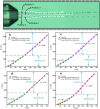
Scatter plot of particle displacement with time under different power, and the straight line is the result of fitting scatter plot.
Fig. 6.
Fig. 6.
When the output power of the fiber end is 140.7 mw, the relationship between particle displacement and time under different flow rate is obtained. (a) The relationship between particle displacement and time when the flow rate is 15 mbar. (b) The trajectory of the particle when the flow rate is 15 mbar. (c) The relationship between particle displacement and time when the flow rate is 33 mbar. (d) The trajectory of the particle when the flow rate is 33 mbar. (e) The relationship between particle displacement and time when the flow rate is 50 mbar. (f) The trajectory of the particle when the flow rate is 50 mbar.
Fig. 7.
Fig. 7.
The trajectories of particles flowing out from different positions, when the injection pressure is 19 mbar and the output power of the fiber end is 150.1 mw. (a) Trajectories of four different position. The relationship between the position and time: (b) particle 1. (c) particle 2. (d) particle 3. (e) particle 4.
Fig. 8.
Fig. 8.
The analysis diagram of particle motion in the emission area. (a) The motion process diagram of the emission area. (b) The calculated particle velocity curve. (c) The enlarging diagram of the velocity change curve in the overshoot region. (d) The relationship between the moving distance and time in the emission area.

Similar articles

References

    1. Lashkaripour A., Silva R., Densmore D., “Desktop micromilled microfluidics,” Microfluid. Nanofluid. 22(3), 31 (2018).10.1007/s10404-018-2048-2 - DOI
    1. Gao Y., Wu M., Lin Y., et al. , “Acoustic bubble-based bidirectional micropump,” Microfluid. Nanofluid. 24(4), 29 (2020).10.1007/s10404-020-02334-6 - DOI
    1. Bissen A., Yunussova N., Myrkhiyeva Z., et al. , “Unpacking the packaged optical fiber bio-sensors: understanding the obstacle for biomedical application,” Front. Bioeng. Biotechnol. 12, 1401613 (2024).10.3389/fbioe.2024.1401613 - DOI - PMC - PubMed
    1. Ikeda M., Imai S., “Basic study of micro-pumps for medication driven by chemical reactions,” IEICE Trans. Electron. 106(6), 253–257 (2023).10.1587/transele.2022OMS0007 - DOI
    1. Revathi S., Padmanabhan R., “Design and development of piezoelectric composite-based micropump,” J. Microelectromech. Syst. 27(6), 1105–1113 (2018).10.1109/JMEMS.2018.2870949 - DOI

LinkOut - more resources