

Miniaturised implantable circular polarized antenna with a high ARBW
- PMID: 40333944
- PMCID: PMC12057919
- DOI: 10.1371/journal.pone.0321670
Miniaturised implantable circular polarized antenna with a high ARBW
Abstract
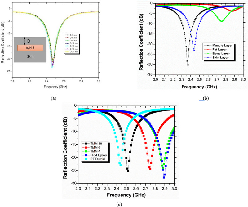
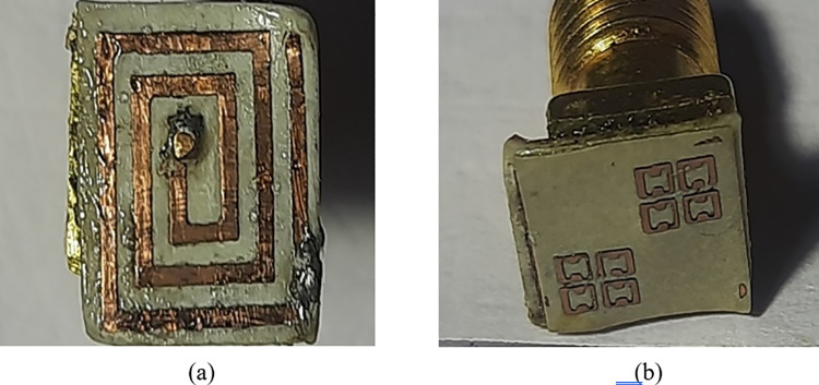
For biological applications, this communication uses an implanted antenna loaded with metamaterial and a sorting pin. The suggested antenna operates at 2.44 GHz in the ISM band. The first antenna's resonant frequency is lowered from 2.53 GHz to 2.46 GHz by applying a sorting pin. This causes the antenna to become circularly polarized and have an ARBW of 580 MHz (2.15 GHz - 2.73 GHz). Strong CP behavior with an ARBW of 830 MHz from 2.01 GHz to 2.84 GHz in the ISM band is produced by incorporation of an H-shaped metamaterial on the antenna's superstrate. Additionally, the reasonable value of the specific absorption rate improved from 960.5 to 952.1. Highlights of the suggested antenna include its miniature size (10.67 mm3), strong CP properties, the significant value of SAR 952.1 W/KG, and unslotted ground plane to detract from designing labyrinthine backscattering radiation. After building the recommended antenna, experiments are conducted using a skin-mimicking gel solution that approximates the electrical characteristics of human skin tissues at 2.44 GHz. In the ISM band, actual and simulated impedance bandwidths of 90 MHz and 110 MHz are acquired, respectively. Together with parametric analysis, simulation and measurement results are consistent.
Copyright: © 2025 Nehra et al. This is an open access article distributed under the terms of the Creative Commons Attribution License, which permits unrestricted use, distribution, and reproduction in any medium, provided the original author and source are credited.
Conflict of interest statement
The authors have declared that no competing interests exist.
Figures


References
-
- Liu XY, Wu ZT, Fan Y, Tentzeris EM. A miniaturized CSRR loaded wide-beamwidth circularly polarized implantable antenna for subcutaneous real-time glucose monitoring. IEEE Antennas Wirel Propag Lett. 2016;16:577–580.
-
- Bahrami H, Mirbozorgi SA, Ameli R, Rusch LA, Gosselin B. Flexible, polarization-diverse UWB antennas for implantable neural recording systems. IEEE Trans Biomed Circuits Syst. 2015;10(1):38–48. - PubMed
-
- Garoby R, Vergara A, Danared H, Alonso I, Bargallo E, Cheymol B, et al. Corrigendum: The European Spallation Source Design (2018 Phys. Scr. 93 014001). Phys Scr. 2018;93(12):129501. doi: 10.1088/1402-4896/aaecea - DOI
-
- Wang Q, Sihvola A, Qi J. A Novel Procedure To Hybridize The Folded Transmitarray and Fabry Perot Cavity With Low Antenna Profile and Flexible Design Frequency. IEEE Antennas Wirel Propag Lett. 2024.
MeSH terms
LinkOut - more resources
Full Text Sources
Miscellaneous
