. 2025 Jun 11;5(2):100211.
doi: 10.1016/j.bpr.2025.100211. Epub 2025 May 5.

Image-based 3D active sample stabilization on the nanometer scale for optical microscopy

Affiliations

Image-based 3D active sample stabilization on the nanometer scale for optical microscopy

Jakob Vorlaufer et al. Biophys Rep (N Y). .

Abstract

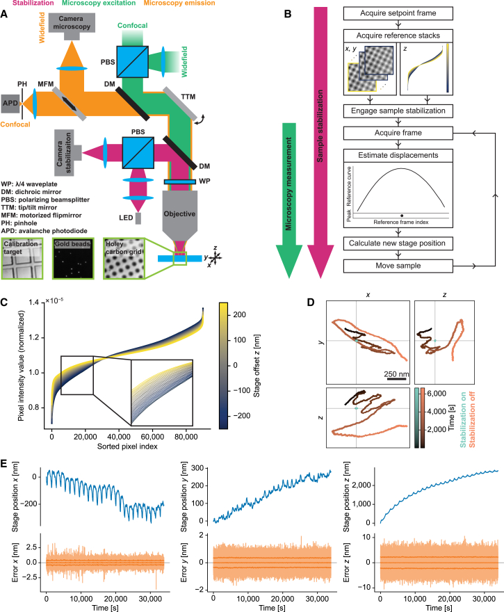
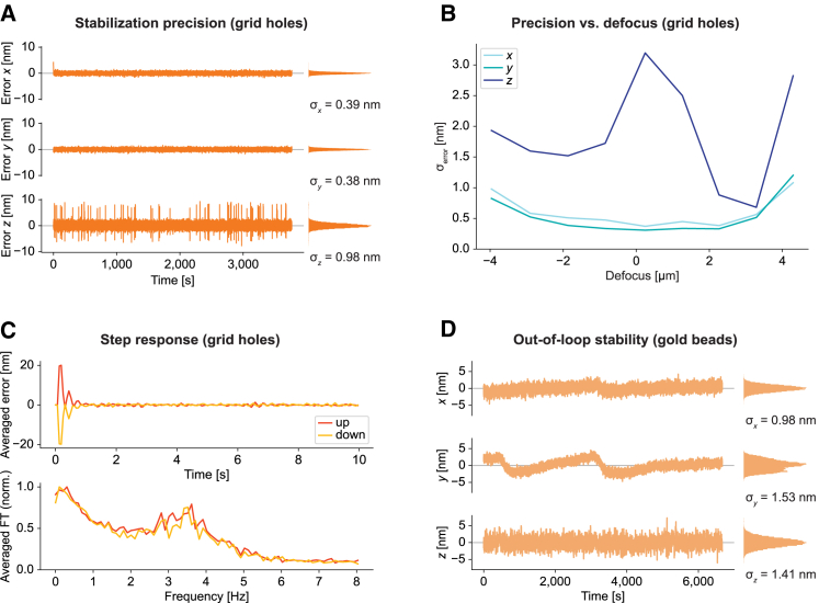
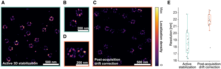
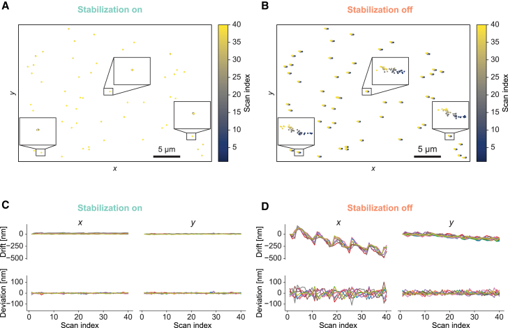
Super-resolution microscopy often entails long acquisition times of minutes to hours. Since drifts during the acquisition adversely affect data quality, active sample stabilization is commonly used for some of these techniques to reach their full potential. Although drifts in the lateral plane can often be corrected after acquisition, this is not always possible or may come with drawbacks. Therefore, it is appealing to stabilize sample position in three dimensions (3D) during acquisition. Various schemes for active sample stabilization have been demonstrated previously, with some reaching sub-nanometer stability in 3D. Here, we present a scheme for active drift correction that delivers the nanometer-scale 3D stability demanded by state-of-the-art super-resolution techniques and is straightforward to implement compared to previous schemes capable of reaching this level of stabilization precision. Using a refined algorithm that can handle various types of reference structure, without sparse signal peaks being mandatory, we stabilized sample position to ∼1 nm in 3D using objective lenses both with high and low numerical aperture. Our implementation requires only the addition of a simple widefield imaging path and we provide an open-source control software with graphical user interface to facilitate easy adoption of the module. Finally, we demonstrate how this has the potential to enhance data collection for diffraction-limited and super-resolution imaging techniques using single-molecule localization microscopy and cryo-confocal imaging as showcases.


Conflict of interest statement

Declaration of interests The authors declare no competing interests.

Figures

Figure 1
Figure 1
Active stabilization concept. (A) Schematics of optical path for sample stabilization (magenta), comprising a widefield imaging path using near-infrared light, combined with the microscopy path (green/orange) via a dichroic mirror (DM). For further details, see Fig. S1. Bottom: representative raw images of different structures used for stabilization. Right: holey carbon film commonly used in cryo-fluorescence imaging and electron microscopy. Middle: gold beads immobilized on a coverslip. Left: magnification calibration target with 10-μm tiles. Individual images have approximately 23-μm edge length. (B) Stabilization workflow. After choosing an ROI and acquisition of reference stacks (data shown correspond to one of the datasets used in Fig. 2B), the scheme estimates displacements in each iteration of the active feedback loop by comparing camera frames against the reference stacks and actuates on sample position. Microscopy measurements are started once feedback is engaged (indicated by arrows left of the workflow diagram). (C) Normalized pixel intensity as a function of intensity-sorted pixel index for each frame (color coded) of the reference stack along the z direction. Enlarged view of the data in (B). Curves for the individual frames of the reference stack (spaced 20 nm along z) can be discerned as separate lines in the magnified view. (D) Position of an individual gold bead on a coverslip over time with and without sample stabilization, tracked in the microscopy path for 1 h 51 min. For stabilization of sample position, a distinct set of gold beads on the same coverslip was used in the stabilization path. (E) Long-term stabilization measurement on a holey carbon film. The blue curves show the stage movement applied to compensate drifts. Error signals reflecting the residual deviations from the setpoint sample position (semi-transparent orange curves) are centered on 0. The central solid orange line shows the rolling average of the error signals across 1000 data points. The lines above and below represent the standard deviation across the same window. The prominent periodic stage movements are correlated with fluctuations of laboratory temperature.
Figure 2
Figure 2
Performance characterization. (A) Representative measurement of the in-loop stability, as derived from error signals, of the active stabilization unit on holey carbon grids. The measurement was acquired at a slight positive defocus (sample shifted toward objective) with an air objective with 0.75 NA. Histograms of the respective error curves are displayed to their right together with standard deviation σ. Along the optical axis, there were occasional spikes, which may be related to vibrations associated with the fan of the camera. (B) Precision of the active stabilization for different defocus positions using the same sample as in (A). The focus position was determined by eye as the position where the structure appeared sharpest. The sample was then moved manually in steps of 1 μm along z, and the stabilization was engaged at each position. Each curve shows the standard deviation of the error signals (σerror) of measurements of ∼200-s duration. (C) Step response of the active sample stabilization. Dynamic response of the system tested by applying offsets to the stage position in steps of ±20 nm every 10 s. Curves shown here represent averages of 10 steps in each direction along the x axis. Raw data as well as corresponding measurements for the other axes are shown in Fig. S4. (D) Position of an individual gold bead on a coverslip over time, imaged in the microscopy path. In the stabilization path, a set of gold beads in a different ROI was used for stabilizing sample position. Residual drifts included relative drifts of the microscopy vs. stabilization path of the microscope.
Figure 3
Figure 3
Active stabilization for dSTORM imaging of nuclear pores. (A and B) Two ROIs at different zoom factors of a dSTORM reconstruction of nuclear pores with active stabilization engaged, showing the ring-like arrangement of the subunits. Observed variability between individual pores includes biological factors and imperfections in labeling. (C and D) Analogous measurement from different cells on the same coverslip without active stabilization, using RCC-based drift correction after acquisition. See Fig. S5 for additional imaging data. (E) Resolution of reconstructions with active 3D stabilization or post-acquisition drift correction displayed as boxplots (lower whisker: lowest data point within 1.5× interquartile range below first quartile, first quartile, median, third quartile, upper whisker: highest data point within 1.5× interquartile range above third quartile). Datapoints represent individual ROIs recorded across two individual measurements for each of the two conditions on the same coverslip. See section materials and methods for details on resolution measurements.
Figure 4
Figure 4
Cryo-confocal imaging. (A and B) Tracking position of fluorescent beads at cryogenic temperature over 40 confocal scans with sample stabilization engaged (A) or switched off (B), with beads embedded in vitreous ice after plunge-freezing. Insets: 10-fold enlarged views of trajectories of manually selected beads. Tracks differed from each other, reflecting drifts within individual scans, as beads were stably embedded in the vitreous ice. (C and D) Top row: drifts of nine manually selected beads as a function of scan index from the same datasets as (A) and (B), respectively. Bottom row: deviations of bead positions relative to the mean position of the selected beads for every scan. Display ranges of corresponding panels in (C) and (D) were identical to facilitate comparison of the associated spatial scales with and without stabilization.

Similar articles

References

    1. Huang B., Bates M., Zhuang X. Super resolution fluorescence microscopy. Annu. Rev. Biochem. 2009;78:993–1016. - PMC - PubMed
    1. Sahl S.J., Hell S.W., Jakobs S. Fluorescence nanoscopy in cell biology. Nat. Rev. Mol. Cell Biol. 2017;18:685–701. - PubMed
    1. Lelek M., Gyparaki M.T., et al. Zimmer C. Single-molecule localization microscopy. Nat. Rev. Methods Primers. 2021;1:39. - PMC - PubMed
    1. Power R.M., Tschanz A., et al. Ries J. Build and operation of a custom 3D, multicolor, single-molecule localization microscope. Nat. Protoc. 2024;19:2467–2525. - PubMed
    1. Wang Y., Schnitzbauer J., et al. Huang B. Localization events-based sample drift correction for localization microscopy with redundant cross-correlation algorithm. Opt. Express. 2014;22:15982–15991. - PMC - PubMed

LinkOut - more resources