. 2025 Jul;21(26):e2502767.
doi: 10.1002/smll.202502767. Epub 2025 May 8.

Transfer-Printed Wrinkled PVDF-Based Tactile Sensor-Nanogenerator Bundle for Hybrid Piezoelectric-Triboelectric Potential Generation

Affiliations

Transfer-Printed Wrinkled PVDF-Based Tactile Sensor-Nanogenerator Bundle for Hybrid Piezoelectric-Triboelectric Potential Generation

Kamal Kumar Meena et al. Small. 2025 Jul.

Abstract

Triboelectric sensors are known for their ultrahigh sensitivity and wide-range detectability of tactile force/pressure, all while being self-powered. However, the energy harvesting efficiency of triboelectric nanogenerators (TENGs) is often limited by relatively low output power density, when compared to other state-of-the-art microgenerators. To address this challenge and achieve high force/pressure detection while maintaining excellent tactile resolution, a hybrid nanogenerator is proposed that comprises of both triboelectric and piezoelectric components within a ferroelectric polyvinylidene fluoride (PVDF) polymer matrix. To enhance tactile sensitivity, a coupled transfer printed-spin coating technique is introduced to imprint wrinkled silicone structuring with tunable periodicity and amplitude directly onto PVDF. The hybrid output voltage of the wrinkled PVDF-based TENG utilizing the ferroelectric β phase of PVDF (FE-TENG_5) shows an impressive ≈200% increase compared to pristine FE-TENG. The highest power density (0.9 mW cm-2) corresponds to FE-TENG with the periodicity of 5 µm. Remarkably, the imprinted FE-TENGs can detect even the slightest tactile force (<2 N), while the hybrid mechanism ensures a broad force sensing range, extending up to 100 N before saturation. This exceptional performance establishes the imprinted PVDF-based FE-TENG as a versatile tactile sensing platform for a range of cutting-edge applications, particularly in electronic skin and next-generation microelectronics.

Keywords: imprinted PVDF; piezoelectric‐triboelectric hybrid potential; self‐powered tactile sensor; transfer printing; triboelectric nanogenerator.


Conflict of interest statement

The authors declare no conflict of interest.

Figures

Figure 1
Figure 1
Fabrication, structural replication, and morphological characterization of wrinkled PVDF surfaces. a) A schematic of the spin coating process used for the formulation of imprinted PVDF films. b) An illustration depicting the wrinkled PDMS structure as a template and the imprinted PVDF structure as replica. c) Pictorial demonstration of curvature for wrinkled and imprinted PVDF. d) Key morphological parameters of the imprinted PVDF structure, with P representing the periodicity (distance between two consecutive peaks) and A denoting the amplitude (vertical distance between crest and valley of the profile). e) SEM images of the imprinted PVDF surfaces exhibiting approximate periodicities of ≈5 µm (i), ≈7 µm (ii), ≈26 µm (iii), and ≈40 µm (iv). f) Confocal microscopic images of the wrinkled PDMS template and the corresponding imprinted PVDF patterns, showing periodicities of 4.68 ± 0.11 µm (i) and 4.72 ± 0.66 µm (ii), as well as 39.86 ± 5.77 µm g‐i) and 40.07 ± 5.30 µm g‐ii), respectively. Scale bars: 10 µm in (f) and 100 µm in (g). h) Line profile comparisons between the wrinkled PDMS template and the imprinted PVDF structures, highlighting periodicities around ≈5 µm (i) and ≈40 µm (ii). The locations of the extracted profiles are indicated in (f,g).
Figure 2
Figure 2
Schematic and performance analysis of the imprinted PVDF nanogenerator. a) Illustration of the multimodal imprinted PVDF sensor. b) Representative voltage‐time data demonstrating the sensor's response under cyclic pressure and the associated charge accumulation dynamics. c) Stepwise operational mechanism detailing (i) initial state, (ii) contact initiation, (iii) deformation, (iv) recovery, and (v) separation, indicating generation of both piezoelectric and triboelectric charges in response to mechanical force. d,e) Voltage responses measured under varied cyclic pressures (1–5 bar) at a constant frequency of 1 Hz. f) The peak‐to‐peak voltage demonstrates a linear increase with applied pressure, thereby improving energy harvesting capabilities under different load conditions (1–5 bar). g) Optimization analysis of FE‐TENG_5 reveals how variations in external resistance (20 kΩ–47 MΩ) affect both the voltage and power density, ultimately identifying the conditions that yield the maximum power density.
Figure 3
Figure 3
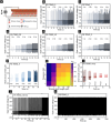
Frequency‐dependent electrical performance and stability of imprinted PVDF sensors. a) Schematic illustration of triboelectric and piezoelectric charge generation under mechanical deformation. b–f) Comparison of open‐circuit voltage (V OC) outputs measured across frequencies from 1 to 5 Hz for sensors featuring periodic surface structures of approximately 5, 7, 26, 40 µm and non‐patterned (FE‐TENG_0), respectively. g) Short‐circuit current output of the FE‐TENG_5 device at different frequencies, demonstrating consistent and stable current generation. h) Color mapping visualizing the combined influence of the imprinted PVDF's periodicity and vertical contact–separation mode frequency on the triboelectric VOC, providing insights into device optimization. i) Comparison of short‐circuit current at 1 Hz for various wrinkle periodicities and non‐patterned (NP) control, highlighting morphology‐dependent electrical output. j,k) Long‐term stability evaluation under repeated cyclic impacts (up to 3000 cycles) at an applied pressure of 3 N and a frequency of 5 Hz, confirming the sensor's robustness and reliability over extended use.
Figure 4
Figure 4
Ultra‐sensitive tactile sensing performance of the imprinted PVDF sensor: a) Finite element method (FEM)‐based numerical simulation illustrating the enhanced surface charge distribution and triboelectric potential of the microstructured sensor. b) Demonstration of the sensor's precise force detection capability using calibrated weights ranging from 100 to 300 g. c) Dynamic response of the device under simultaneous bending and twisting, illustrating robust output under complex mechanical deformations. d,e) Finger‐tapping frequency detection using the FE‐TENG_5 device, which can precisely count the number of taps based on the number of full waveforms, with a resolution of up to 10 Hz. Photographs show the actual test setup. f,g) Force sensing measurements under varying foot‐tapping frequencies, highlighting the corresponding V OC responses and overall sensitivity of the sensor. h) Schematic representation of a 3D‐printed thermoplastic polyurethane (TPU) capsule used for controlled tactile testing, enabling consistent and reproducible sensor performance assessments.

Similar articles

References

    1. Liu Z., in Global Energy Interconnection (Ed: Liu Z.), Academic Press, Boston: 2015, pp. 1–64.
    1. Gielen D., Boshell F., Saygin D., Bazilian M. D., Wagner N., Gorini R., Energy Strategy Rev. 2019, 24, 38.
    1. Verners O., Šutka A., Arief I., Das A., Mālnieks K., Lungevičs J., Mater. Sci. Eng., B 2025, 317, 118140.
    1. Valkhof B., Kemene E., Stark J. Data volume is soaring, Here's how the ICT sector can sustainably handle the surge, https://www.weforum.org/stories/2024/05/data‐growth‐drives‐ict‐energy‐in... (accessed: December 2024).
    1. Kundu A., Arief I., Mandal S., Meena K. K., Krause B., Staudinger U., Mondal T., Wießner S., Das A., ACS Appl. Mater. Interfaces 2024, 16, 53083. - PubMed

LinkOut - more resources