. 2025 Jul 1;32(Pt 4):884-898.
doi: 10.1107/S1600577525003078. Epub 2025 May 13.

Optimizing a photon absorber using conformal cooling channels and additive manufacturing in copper

Affiliations

Optimizing a photon absorber using conformal cooling channels and additive manufacturing in copper

Younes Chahid et al. J Synchrotron Radiat. .

Abstract

Many of the 70 synchrotron facilities worldwide are undergoing upgrades to their infrastructure to meet a growing demand for increased beam brightness with nanometre-level stability. These upgrades increase the mechanical and thermal challenges faced by beamline components, creating opportunities to apply novel methodologies and manufacturing processes to optimize hardware performance and beam accuracy. Absorbers are important beamline components that rely on water-cooled channels to absorb thermal energy from excess light caused by synchrotron radiation or photon beams created by insertion devices, all within a limited volume, to protect downstream equipment and ensure safe, reliable operation. Additive manufacturing (AM) has been shown to meet criteria relevant to synchrotron environments like leak tightness and vacuum compatibility. However, there is a research gap on the heat transfer and pressure drop impact of different AM conformal cooling channel geometries, as well as the print quality of AM copper parts using low-power infrared lasers and their compliance with absorber requirements. In this study, an intermediate model of a Diamond Light Source photon absorber was optimized to incorporate AM conformal cooling channels, leading to two concept designs named `Horizontal' and `Coil'. When compared with the baseline design, the lightweight Horizontal concept performed the best in this study, with simulations showing a maximum temperature drop of 11%, a calculated pressure drop reduction of 82%, a mass reduction of 86%, and the consolidation of 21 individually brazed pipes into a single manifold. The AM print quality and compliance with the synchrotron environment was examined by producing custom benchmark artefacts and measuring their surface roughness, dimensional accuracy and porosity levels, which are characteristics that can affect heat absorption, structural integrity, thermal conductivity and vacuum performance. The study demonstrates the benefits and addresses outstanding challenges in reducing thermal fatigue, as well as the size, vibrations and energy consumption of AM absorbers.

Keywords: 3D printing; additive manufacturing; heat transfer; particle accelerator; pressure drop.


Figures

Figure 1
Figure 1
Full size conventional absorber CAD design with a length of 600 mm (top). Cross section of the conventional CAD-design, showing an example of the beam in red, coming from the insertion device, and hitting the BTS which is angled at 3.5° to the source (bottom).
Figure 2
Figure 2
Example of a conventionally manufactured copper absorber showing vacuum brazed copper cooling pipes (left). Assembled version of an absorber in the DLS synchrotron front end with vacuum brazed stainless steel pipes (right).
Figure 3
Figure 3
Conventional full size design (a), ROIs of different beam configurations, touching different BTS and resulting in different maximum temperatures (b), and trimmed design forming the intermediate model used for concept development (c).
Figure 4
Figure 4
Full size conventional CAD cross section showing the thermal simulation result in Ansys (top). Intermediate model thermal simulation result made using nTop and cross section showing cooling channels (bottom).
Figure 5
Figure 5
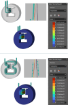
Design of the cooling channels used in the intermediate model (left), in the Horizontal model (middle) and in the Coil model (right).
Figure 6
Figure 6
Horizontal model steady state thermal simulation and cross section (top). Coil model steady state thermal simulation and cross section (bottom).
Figure 7
Figure 7
Cooling water interface maximum temperature of ∼107°C for the Horizontal design (left) and ∼122°C for the Coil design. Both temperatures are below the maximum boiling temperature of ∼165°C for DLS synchrotron water operating at 6 bar (gauge pressure).
Figure 8
Figure 8
3D printed resin prototypes of the Horizontal and Coil design concepts used for experimental pressure drop measurements.
Figure 9
Figure 9
Calculated and experimentally measured pressure drops of the different manifold designs.
Figure 10
Figure 10
Hydraulic diagram showing the test rig setup used to measure the pressure drop of the Horizontal and Coil designs.
Figure 11
Figure 11
Two custom-made benchmark artefacts with support-less pipes and cylinder wall thickness design (left) and another benchmark artefact with teardrop shape pipes and gyroid wall thickness design (right), both 3D printed in copper, using an EOS M290.
Figure 12
Figure 12
Profile surface roughness measurement of the outer upper surface (a), up-skin of the 12 mm pipe (b), and down-skin of the 12 mm pipe (c).
Figure 13
Figure 13
Cylinder wall thickness measurement using CMM stylus (top), and gyroid wall thickness measurement using CMM camera (bottom).
Figure 14
Figure 14
Microscope images showing the different contour forms of the cylinders with wall thicknesses of 0.25 mm, 0.5 mm, 1 mm and 1.5 mm (from top right to bottom left). These cylinders served as a reference to guide the selection of the pipe wall thickness and shell wall thickness for the copper printed absorber.
Figure 15
Figure 15
CMM camera images showing gyroids with wall thicknesses of 0.16 mm, 0.32 mm, 0.64 mm and 0.96 mm (from top right to bottom left). These gyroids served as a reference to guide the selection of the infill wall thickness for the copper printed absorber.
Figure 16
Figure 16
Porosity analysis performed on a ground and polished 18 mm-diameter sample, revealing a 6.20% porosity using a microscope (top), and the shape of different pores using an SEM (bottom).
Figure 17
Figure 17
LPBF process (a), lightweight Coil pipe concept design within the powder bed (b) and without surrounding powder (c).
Figure 18
Figure 18
Transparent CAD model of lightweight Horizontal design (a) and lightweight Coil design (b) showing the gyroid infill in green and cooling channel in blue. Cross section of the lightweight Horizontal (c) and lightweight Coil design (d) showing how the gyroid infill covers the majority of the lightweight Horizontal design but only the upper 16 mm of the lightweight Coil design.
Figure 19
Figure 19
Additive manufactured lightweight Horizontal absorber (left), and lightweight Coil (right) shown in the same orientation as the upward print direction.
Figure 20
Figure 20
Lightweight Horizontal model thermal simulation and cross section.

References

    1. Biffi, C. A., Fiocchi, J., Boldrini, S. & Tuissi, A. (2024). Lasers Manuf. Mater. Process.11, 143–153.
    1. Cacho-Nerin, F., Parker, J. E. & Quinn, P. D. (2020). J. Synchrotron Rad.27, 912–922. - PMC - PubMed
    1. Cengel, Y. (2004). Heat Transfer: A Practical Approach. McGraw-Hill Education (https://books.google.co.uk/books?id=xYASMQAACAAJ).
    1. Cengel, Y. & Cimbala, J. (2013). Fluid Mechanics Fundamentals and Applications, 3rd ed. McGraw-Hill US Higher Education (https://books.google.co.uk/books?id=QZIjAAAAQBAJ).
    1. Çengel, Y. & Ghajar, A. (2015). Heat and Mass Transfer: Fundamentals and Applications, Asia Higher Education Engineering/Computer Science Mechanica. McGraw Hill Education (https://books.google.co.uk/books?id=1YPhoAEACAAJ).

LinkOut - more resources