. 2025 May 15;46(13):e70126.
doi: 10.1002/jcc.70126.

GPU Accelerated Hybrid Particle-Field Molecular Dynamics: Multi-Node/Multi-GPU Implementation and Large-Scale Benchmarks of the OCCAM Code

Affiliations

GPU Accelerated Hybrid Particle-Field Molecular Dynamics: Multi-Node/Multi-GPU Implementation and Large-Scale Benchmarks of the OCCAM Code

Rosario Esposito et al. J Comput Chem. .

Abstract

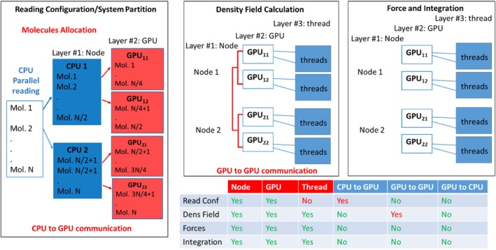
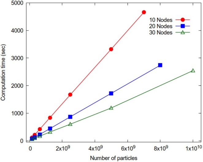
A parallelization strategy for hybrid particle-field molecular dynamics (hPF-MD) simulations on multi-node multi-GPU architectures is proposed. Two design principles have been followed to achieve a massively parallel version of the OCCAM code for distributed GPU computing: performing all the computations only on GPUs, minimizing data exchange between CPU and GPUs, and among GPUs. The hPF-MD scheme is particularly suitable to develop a GPU-resident and low data exchange code. Comparison of performances obtained using the previous multi-CPU code with the proposed multi-node multi-GPU version are reported. Several non-trivial issues to enable applications for systems of considerable sizes, including large input files handling and memory occupation, have been addressed. Large-scale benchmarks of hPF-MD simulations for system sizes up to 10 billion particles are presented. Performances obtained using a moderate quantity of computational resources highlight the feasibility of hPF-MD simulations in systematic studies of large-scale multibillion particle systems. This opens the possibility to perform systematic/routine studies and to reveal new molecular insights for problems on scales previously inaccessible to molecular simulations.

Keywords: GPU‐accelerated molecular dynamics; coarse‐graining; hybrid particle‐field method; large‐scale simulations.


Conflict of interest statement

The authors declare no conflicts of interest.

Figures

SCHEME 1
SCHEME 1
Coarse‐graining horizontal (upper panel) and vertical approaches (lower panel) are compared. In horizontal approaches, like hybrid particle‐field MD, the two scales (particle and field) coexist in the same model. In contrast, vertical approaches are based on particle reduction, and effective interactions are parametrized to reproduce properties of models on a microscopic scale.
FIGURE 1
FIGURE 1
(A) Iterative scheme for hPF‐MD simulations; (B) simplified example (2D) for particle assignment to a mesh following the PIC scheme. Fraction of particles is assigned proportionally to the area of a rectangle whose diagonal is the segment connecting the particle and the lattice point on the opposite side of the cell (empty crosses indicate the staggered lattice where the derivatives are defined).
SCHEME 2
SCHEME 2
Diagrams reporting the main operations: Reading/partition (top left), density field calculation (top central), force calculation and integrations (top right) are reported. Different layers, exploited in the proposed parallelization, and communication operations needed are reported in the table on the bottom of the Scheme.
FIGURE 2
FIGURE 2
Example input configuration file for OCCAM code. On each line, all necessary information for a given particle belonging to a given molecule is provided: Particle number, label, type, number of bonds formed, Cartesian coordinates (and eventually velocities) and connectivity (index of the particles forming bonds with the particle).
FIGURE 3
FIGURE 3
Input data describing the topology, position, velocity, and thermodynamic ensemble of the simulation molecules distributed among the nodes. In each node, a single CPU is responsible for partitioning the partial data among the GPUs.
FIGURE 4
FIGURE 4
Dashed lines represent bonds between particles from two different elements in the bonding list sharing one atom. Each bond is assigned to a separate thread for concurrent computation. The threads calculate contributions to the bonding force acting upon the atom “m”, highlighting the need for atomic functions to maintain data consistency during parallel processing.
SCHEME 3
SCHEME 3
Pseudocodes describing the previous implementation for the calculation of: (A) density gradient, (B) interpolation of density and gradient at particle position compared with (C) proposed memory saving implementation.
FIGURE 5
FIGURE 5
Illustration of a possible spatial distribution of some molecules assigned to a GPU and corresponding lattice points (in transparent gray) where the density is assigned. Usually, more than one particle contribute to the density field calculated at the same lattice point.
FIGURE 6
FIGURE 6
Multi‐node, multi‐GPU parallelization scheme adopted for the calculation of the density fields. The partial density ϕij calculated from molecules owned by GPU j of node i (GPU ij ). The total density field ϕ, calculated from all molecules in the simulated system, is obtained by summing up partial densities ϕij using the CUDA‐aware technology, which enables efficient data exchange among GPUs within the same node and among GPUs belonging to different nodes.
FIGURE 7
FIGURE 7
Performances comparison between reduced and atomic sums for calculations of global physical properties in a molecular simulation system.
FIGURE 8
FIGURE 8
Computation times as a function of particle number: Performances of multi‐CPU OCCAM on 100 cores (black); results obtained from different multi‐GPU setups: One GPU (red), 4 GPUs one node (blue), 40 GPUs 10 nodes (green.)
FIGURE 9
FIGURE 9
Computation times (5 × 104 timesteps) vs. total Particle for different number of multi GPU nodes (each node 4 GPUs): 5 (black), 10 (red), 20 (blue) and 30 nodes (green) have been employed.
FIGURE 10
FIGURE 10
Snapshot of a coarse‐grained model of a DPPC lipid bilayer in water. The number of beads of the depicted system is 1.03 × 109 and the benchmark simulation has been run for 1 million timesteps.
FIGURE 11
FIGURE 11
Run times (50.000 steps in the NVT ensemble) for CG water model as function of number of particles for 10, 20, and 30 nodes (red, blue, and green curves, respectively).
FIGURE 12
FIGURE 12
Strong scaling behavior of OCCAM code. Speed‐ups are calculated as the ratio t5/t between running times on five nodes (20 GPUs) and actual running times.

References

    1. van Gunsteren W. F., Dolenc J., and Mark A. E., “Molecular Simulation as an Aid to Experimentalists,” Current Opinion in Structural Biology 18, no. 2 (2008): 149–153, 10.1016/j.sbi.2007.12.007. - DOI - PubMed
    1. Brooks C. L., MacKerell A. D., Post C. B., and Nilsson L., “Biomolecular Dynamics in the 21st Century,” Biochimica et Biophysica Acta (BBA) ‐ General Subjects 1868, no. 2 (2024): 130534, 10.1016/j.bbagen.2023.130534. - DOI - PMC - PubMed
    1. De Nicola A., Touloupidis V., Kanellopoulos V., Albunia A. R., and Milano G., “A Combined Experimental and Molecular Simulation Study on Stress Generation Phenomena During the Ziegler‐Natta Polyethylene Catalyst Fragmentation Process,” Nanoscale Advances 4 (2022): 5178–5188, 10.1039/d2na00406b. - DOI - PMC - PubMed
    1. Shevlin S., Castro B., and Li X., “Computational Materials Design,” Nature Materials 20, no. 6 (2021): 727, 10.1038/s41563-021-01038-8. - DOI - PubMed
    1. Sevink G. J. A., Liwo J. A., Asinari P., MacKernan D., Milano G., and Pagonabarraga I., “Unfolding the Prospects of Computational (Bio)materials Modeling,” Journal of Chemical Physics 153, no. 10 (2020): 1–10, 10.1063/5.0019773. - DOI - PubMed

LinkOut - more resources