. 2025 May 16;11(20):eadw1259.
doi: 10.1126/sciadv.adw1259. Epub 2025 May 14.

Achieving symmetric snap-through buckling via designed magnetic actuation

Affiliations

Achieving symmetric snap-through buckling via designed magnetic actuation

Yingchao Zhang et al. Sci Adv. .

Abstract

Symmetric snap-through buckling, although both theoretically achievable and practically advantageous, has remained rare in bistable systems, with most studies favoring asymmetric snapping due to its lower energy barrier. Previous observations of symmetric snapping have been limited to high loading rates. In this work, we present a universal strategy to achieve symmetric snapping under quasi-static conditions by designing magnetization (M)-interface patterns that effectively suppress asymmetric modes. A simplified theoretical model demonstrates that this behavior results from the interplay between pitchfork and saddle-node bifurcations, with predictions validated through simulations and experiments using hard magnetic elastomers. Resisting forces generated by multiple M-interfaces counteract asymmetric snapping, enabling distinct symmetric configurations. Extending this approach to higher-order symmetric snapping, we uncover a quasi-linear scaling law between critical fields and snapping order. These findings establish a robust framework for designing snapping systems with enhanced control and predictability, as demonstrated by a mechanical-magnetic snapping switch, paving the way for advanced applications in precision engineering and magnetic-mechanical actuation.


Figures

Fig. 1.
Fig. 1.. Model system and snapping modes overview.
(A) Schematic representation of the hard ferromagnetic soft elastomer (HME), consisting of an elastomer matrix embedded with hard ferromagnetic particles (MPs). (a to d) Method for fabricating magnetization (M) distributions in HME. The process involves three steps: (b) folding the elastica at specific positions, (c) applying a strong magnetic field to pre-magnetize the folded sample, and (d) unfolding the sample to create the desired magnetization pattern along its length and featuring designed magnetization interfaces at positions s=si. (B) Bistable structures with single-M, triple-M, and five-M configurations, formed through Euler buckling under end-to-end shortening ε. A uniform magnetic field B applied either along (B+) or opposite (B) ez triggers snapping, with equivalent (Eq.) point forces at the M-interfaces. (C) Representative snapping modes: asymmetric snapping for the single-M configuration (left), symmetric snapping for the triple-M configuration (middle), and higher-order symmetric snapping for the five-M configuration (right). The images are selected to highlight key moments of the snapping behavior and do not correspond to uniform time intervals. The complete snapping processes are documented in real time in movies S1 to S3.
Fig. 2.
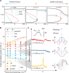
Fig. 2.. Phasing out asymmetric branch to achieve symmetric snapping.
(A) The B-δ relationships for the triple-M configuration are shown for various positions of the first M-interface (S=μ/2). In this load-controlled system, the midpoint vertical displacement δ is plotted on the horizontal axis to intuitively illustrate the stiffness of the asymmetric branch through the slope of the curve. (B) The stiffness of asymmetric branch k versus μ. As μ approaches 0.5, the stiffness of the asymmetric branch diverges, phasing out the asymmetric branch. (C) Phase diagram in the μ1μ2 plane and representative experiments for the five-M configuration, where μ1 and μ2 denote the positions of the first (S=μ1/2) and second (S=μ2/2) M-interfaces, respectively. The solid line in (C) indicates the boundary where asymmetric branch phases out, as its stiffness diverges (k5). Experimental and simulation results confirm symmetric snapping along this boundary. (D) Representative experimental results (ε = 5%) for B+(left, μ2=0.59) and B (right, μ2=0.47) with μ1=0.125 align well with theoretical predictions. The images are selected to highlight key moments of the snapping behavior and do not correspond to uniform time intervals. The complete snapping processes are documented in real time in movies S4 and S5. Asy, asymmetric snapping; Sym, symmetric snapping; Sim, simulation results; Exp, experimental results.
Fig. 3.
Fig. 3.. Bifurcation and phase diagrams for the triple-M configuration.
(A) Bifurcation diagrams showing the transition from a pitchfork bifurcation (μ = 0.9) to a saddle-node bifurcation (μ = 0.51) as the M-interface position (μ) approaches the stiffness divergence boundary. (B) Phase diagram in the με plane. The FvK model predicts constant critical positions (μc±0.62), while the Kirchhoff model reveals nonlinear boundaries (solid lines). Dash-dot lines indicate finite element method (FEM) simulation results. (C) Experimental results and intuitive explanation. The left panel plots midpoint rotation angles versus loading frame for symmetric snapping (μ=0.48 and 0.53) and asymmetric snapping (μ=0.23). The right panel illustrates the competition between driving and resisting forces: B produces a W-like shape, B+ forms an M-like shape, and single-M lacks resisting forces, resulting in asymmetric snapping (“S”-like shape). The images are selected to highlight key moments of the snapping behavior and do not correspond to uniform time intervals. The complete snapping processes are documented in real time in movies S6 to S8.
Fig. 4.
Fig. 4.. Phase diagram for the five-M configuration and scaling laws across snapping modes.
(A) Phase diagram for ε=10%, showing regions for asymmetric, symmetric (black markers), and higher-order symmetric snapping (red markers). The colormap represents the critical magnetic field Bc required to trigger snapping. (B and C) Discrete magnetic rod (DMR) simulation results for the five-M configuration (ε=10%). (B) Maximum θmid versus μ1 and μ2. (C) Comparison between DMR simulation results and theoretical predictions. The colormap represents the maximum θmid during the snapping process. (D and E) Representative experimental images of high-order modes. The images are selected to highlight key moments of the snapping behavior and do not correspond to uniform time intervals. The complete snapping processes are documented in real time in movies S8 and S9. (F) Normalized critical field Bc/B3 versus N across various ε, revealing a quasi-linear universal scaling.
Fig. 5.
Fig. 5.. Symmetric snapping in different systems and potential applications.
(A) FEM simulation setup for a different classical bistable structure based on the single-M design. A clamped elastica with single-M design is used (left). Imposing pre-buckling (ε=10%) with symmetric end angles (α = π/12) results in a bistable structure in natural state (middle). Subsequently pushing it to the other stable state gives the inverted state (right). (B and C) Two actuation methods were evaluated: horizontal release (B) and end rotation (C). The rotation angle θmid is plotted against the actuation process [(B) and (C), middle]. Horizontal release and end rotation result in asymmetric snapping under traditional mechanical loading (B = 0). Introducing a resisting force via magnetic field actuation enables symmetric snapping [(B) and (C), right]. See movie S10 for details. BC, boundary condition. (D) Schematic of the mechanical-magnetic snapping switch based on triple-M design. (E to G) Experimental results: magnetic field–induced symmetric snapping lights an light-emitting diode (LED) (E), and traditional mechanical loading induces asymmetric snapping, forming point contact that fails to activate the LED [(F) and (G)]. Scale bars, 3 mm. The images are selected to highlight key moments of the snapping behavior and do not correspond to uniform time intervals. The complete snapping processes are documented in real time in movie S12.

References

    1. Forterre Y., Skotheim J. M., Dumais J., Mahadevan L., How the Venus flytrap snaps. Nature 433, 421–425 (2005). - PubMed
    1. Sachse R., Westermeier A., Mylo M., Nadasdi J., Bischoff M., Speck T., Poppinga S., Snapping mechanics of the Venus flytrap (Dionaea muscipula). Proc. Natl. Acad. Sci. U.S.A. 117, 16035–16042 (2020). - PMC - PubMed
    1. Erbil S. O., Hatipoglu U., Yanik C., Ghavami M., Ari A. B., Yuksel M., Hanay M. S., Full electrostatic control of nanomechanical buckling. Phys. Rev. Lett. 124, 046101 (2020). - PubMed
    1. Bo R., Xu S., Yang Y., Zhang Y., Mechanically-guided 3D assembly for architected flexible electronics. Chem. Rev. 123, 11137–11189 (2023). - PMC - PubMed
    1. Wang Y., Wang Q., Liu M., Qin Y., Cheng L., Bolmin O., Alleyne M., Wissa A., Baughman R. H., Vella D., Tawfick S., Insect-scale jumping robots enabled by a dynamic buckling cascade. Proc. Natl. Acad. Sci. U.S.A. 120, e2210651120 (2023). - PMC - PubMed

LinkOut - more resources