

Design, construction, and deployment of a multi-locus transcranial magnetic stimulation system for clinical use
- PMID: 40383760
- PMCID: PMC12085834
- DOI: 10.1186/s12938-025-01393-6
Design, construction, and deployment of a multi-locus transcranial magnetic stimulation system for clinical use
Abstract
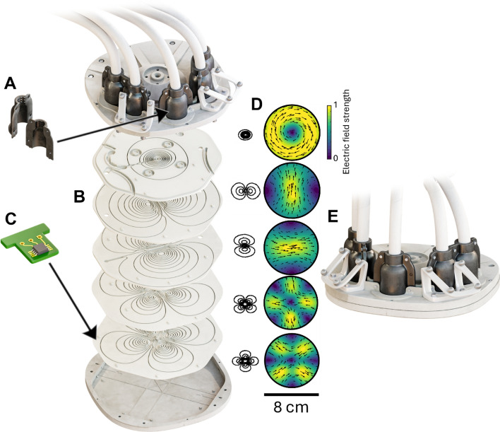
Background: Transcranial magnetic stimulation (TMS) is an established method for noninvasive brain stimulation, used for investigating and treating brain disorders. Recently, multi-locus TMS (mTMS) has expanded the capabilities of TMS by employing an array of overlapping stimulation coils, enabling delivery of stimulation pulses at different cortical locations without physical coil movement. We aimed to design, construct, and deploy an mTMS device and a five-coil array for clinical environment, emphasizing safety of the system.
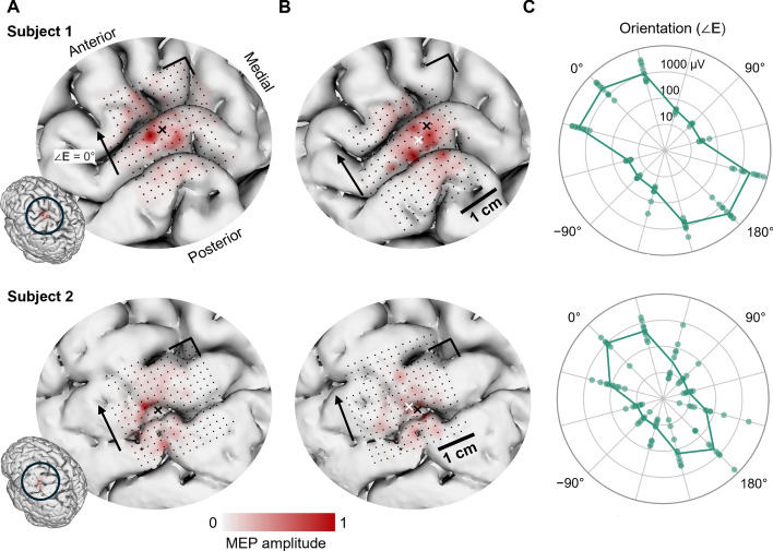
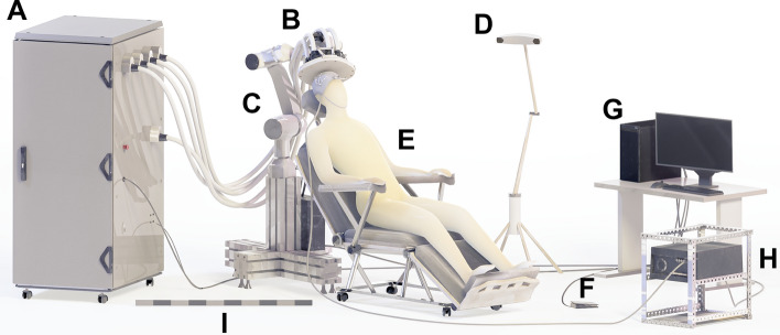
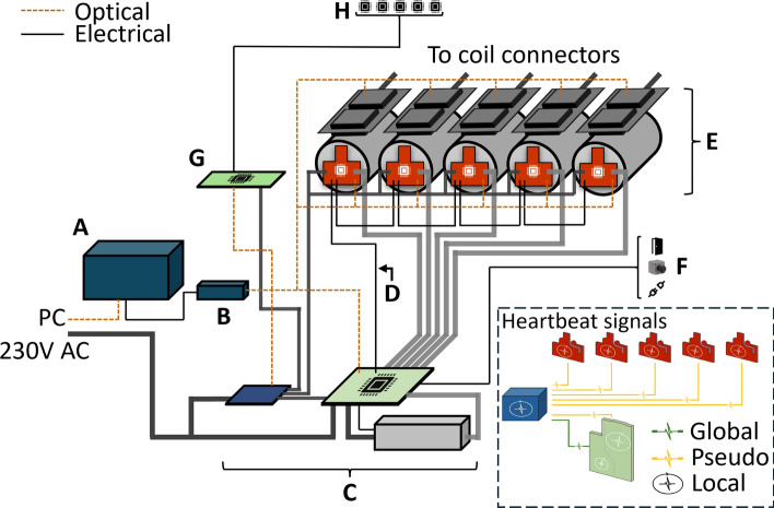
Methods: Our mTMS device is controlled by a field-programmable gate array (FPGA). The power electronics comprises five stimulation channels, each consisting of a high-voltage capacitor connected to a pulse circuit, controlling a single coil in the array. The device contains custom-designed circuit boards, with functions such as monitoring the system state, reporting errors, and delivering pulses. Our design utilizes redundancy in both hardware and firmware to ensure robust operation and safety. We performed an automated motor mapping test to verify the electronic targeting capabilities of the device.
Results: We constructed the mTMS device and deployed it to the Hertie Institute for Clinical Brain Research (Tübingen, Germany). Compared to our earlier prototype, the new design improves patient and operator safety. The motor mapping test confirmed that our device can accurately target stimulation pulses in the cortex.
Significance: mTMS or other similar technologies are currently not available for hospital use. The present device and its installation are major steps toward establishing multicoil TMS as an accessible clinical tool for investigation and treatment of the brain.
Keywords: Functional imaging; Motor mapping; Patient safety; Transcranial magnetic stimulation; mTMS.
© 2025. The Author(s).
Conflict of interest statement
Declarations. Ethics approval and consent to participate: The preliminary testing in two subjects was not considered a study and no ethics approval was required. The participants gave their written, informed consent, and the testing was carried out in accordance with the declaration of Helsinki. For testing more participants, we have now obtained approval by the ethics committee of the Medical Faculty of Tübingen (project number 724/2024MP1). Consent for publication: All authors have read and agreed to the published version of the manuscript. Competing interests: JON and RJI are inventors of patents for mTMS. HS and VHS are inventors of patent applications for TMS and mTMS.
Figures


Similar articles
-
Multi-locus transcranial magnetic stimulation system for electronically targeted brain stimulation.Brain Stimul. 2022 Jan-Feb;15(1):116-124. doi: 10.1016/j.brs.2021.11.014. Epub 2021 Nov 21. Brain Stimul. 2022. PMID: 34818580 Free PMC article.
-
Characterizing an electronic-robotic targeting platform for precise and fast brain stimulation with multi-locus transcranial magnetic stimulation.Phys Med Biol. 2025 Aug 13;70(16). doi: 10.1088/1361-6560/adf36e. Phys Med Biol. 2025. PMID: 40701171
-
Multi-locus transcranial magnetic stimulation with pulse-width modulation.Brain Stimul. 2025 May-Jun;18(3):948-956. doi: 10.1016/j.brs.2025.04.014. Epub 2025 Apr 14. Brain Stimul. 2025. PMID: 40239740
-
Application of transcranial magnetic stimulation for major depression: Coil design and neuroanatomical variability considerations.Eur Neuropsychopharmacol. 2021 Apr;45:73-88. doi: 10.1016/j.euroneuro.2019.06.009. Epub 2019 Jul 5. Eur Neuropsychopharmacol. 2021. PMID: 31285123 Review.
-
Transcranial magnetic stimulation: a possible treatment for TBI.J Head Trauma Rehabil. 2006 Sep-Oct;21(5):437-51. doi: 10.1097/00001199-200609000-00063. J Head Trauma Rehabil. 2006. PMID: 16983227 Review.
References
-
- Barker AT, Jalinous R, Freeston IL. Non-invasive magnetic stimulation of human motor cortex. The Lancet. 1985. 10.1016/S0140-6736(85)92413-4. - PubMed
-
- Weise K, Numssen O, Kalloch B, Zier AL, Thielscher A, Haueisen J, et al. Precise motor mapping with transcranial magnetic stimulation. Nat Protoc. 2023. 10.1038/s41596-022-00776-6. - PubMed
-
- Picht T, Mularski S, Kuehn B, Vajkoczy P, Kombos T, Suess O. Navigated transcranial magnetic stimulation for preoperative functional diagnostics in brain tumor surgery. Neurosurgery. 2009. 10.1227/01.NEU.0000348009.22750.59. - PubMed
-
- Lefaucheur JP, Picht T. The value of preoperative functional cortical mapping using navigated TMS. Neurophysiol Clin. 2016. 10.1016/j.neucli.2016.05.001. - PubMed
MeSH terms
Grants and funding
- 810377/ERC_/European Research Council/International
- 810377/ERC_/European Research Council/International
- 810377/ERC_/European Research Council/International
- 810377/ERC_/European Research Council/International
- 810377/ERC_/European Research Council/International
- 810377/ERC_/European Research Council/International
- 810377/ERC_/European Research Council/International
- 810377/ERC_/European Research Council/International
- 810377/ERC_/European Research Council/International
- 810377/ERC_/European Research Council/International
- 810377/ERC_/European Research Council/International
- 810377/ERC_/European Research Council/International
- 810377/ERC_/European Research Council/International
- 810377/ERC_/European Research Council/International
- 810377/ERC_/European Research Council/International
- 810377/ERC_/European Research Council/International
- 810377/ERC_/European Research Council/International
- 810377/ERC_/European Research Council/International
- 810377/ERC_/European Research Council/International
- 810377/ERC_/European Research Council/International
- 810377/ERC_/European Research Council/International
- 294625/Research Council of Finland
- 349985/Research Council of Finland
- 294625/Research Council of Finland
- 1752/31/2020/Business Finland
- 1752/31/2020/Business Finland
- 1752/31/2020/Business Finland
- 1752/31/2020/Business Finland
- 1752/31/2020/Business Finland
- 1752/31/2020/Business Finland
- 1752/31/2020/Business Finland
- 1752/31/2020/Business Finland
- NNF22OC0080883/Novo Nordisk
- NNF22OC0080883/Novo Nordisk
- NNF22OC0080883/Novo Nordisk
- NNF22OC0080883/Novo Nordisk
- NNF22OC0080883/Novo Nordisk
- NNF22OC0080883/Novo Nordisk
LinkOut - more resources
Full Text Sources
