. 2025 Oct;94(4):1804-1816.
doi: 10.1002/mrm.30563. Epub 2025 May 20.

RF shimming strategy for an open 60-channel RF transmit 7T MRI head coil for routine use on the single transmit mode

Affiliations

RF shimming strategy for an open 60-channel RF transmit 7T MRI head coil for routine use on the single transmit mode

Andrea N Sajewski et al. Magn Reson Med. 2025 Oct.

Abstract

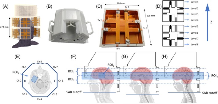
Purpose: To develop an radiofrequency (RF) shimming approach for operating the 2nd Generation Tic Tac Toe RF coil system (60 transmit channels integrated with 32-channel receive insert) for routine use in 7T neuro MRI on the single transmit mode.

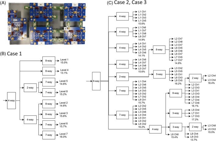
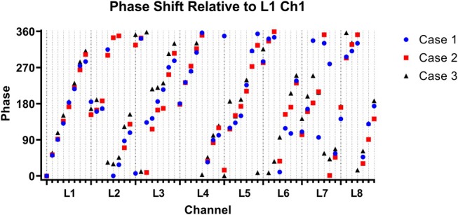
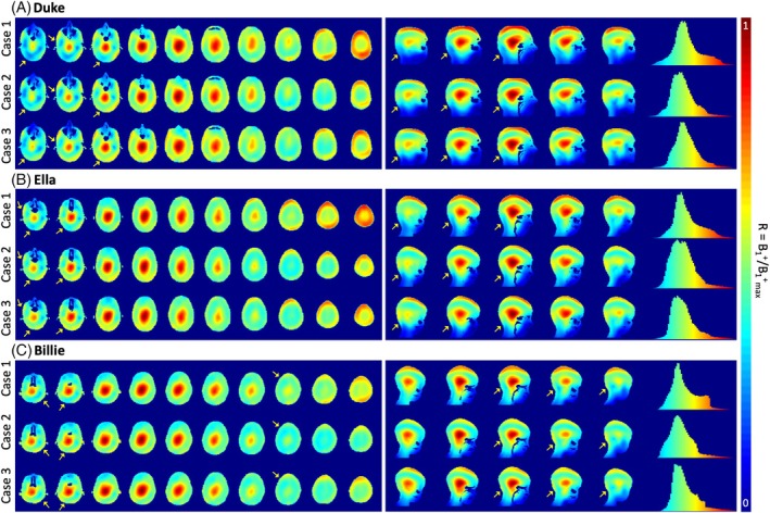
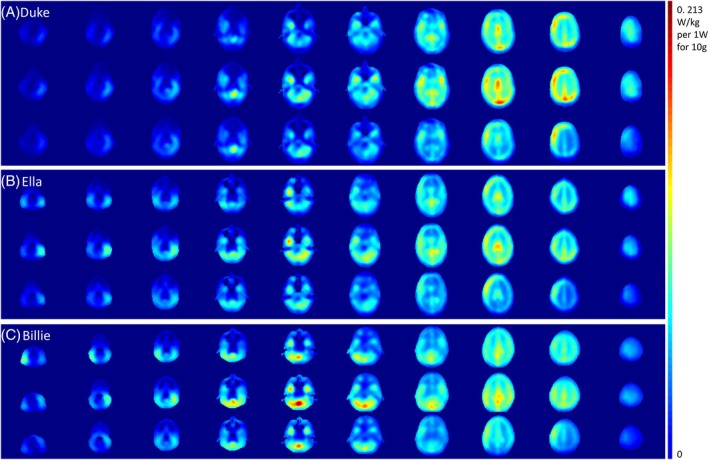
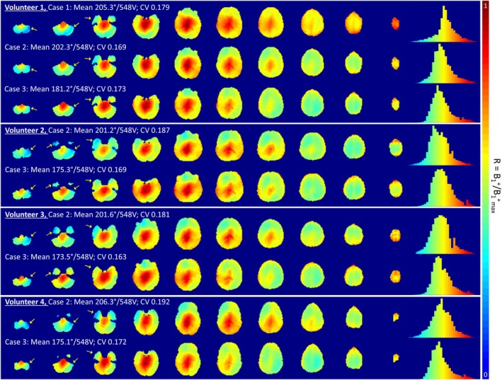
Methods: RF simulations were performed and used to develop non-subject-specific RF shim cases over three anatomically detailed head models: adult male, adult female, and child female. Multi-ROI shimming strategies were developed and implemented. B 1 + $$ {\mathrm{B}}_1^{+} $$ maps and in vivo images were acquired on the single transmit mode of a 7T scanner using the RF shim cases derived from the computer simulations.

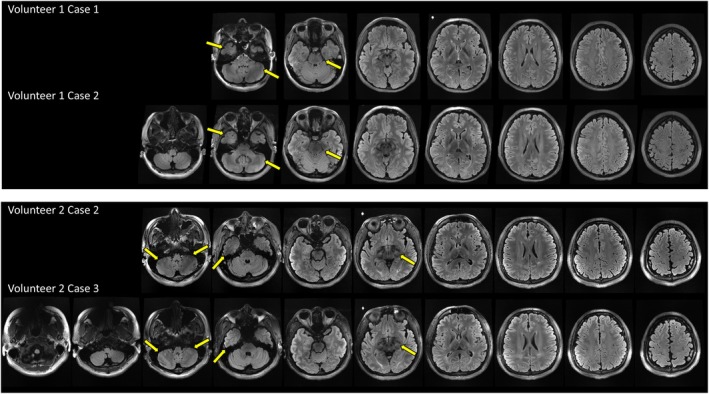
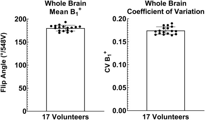
Results: The availability of 60 transmit channels enables more control over B 1 + $$ {\mathrm{B}}_1^{+} $$ efficiency, specific absorption rate (SAR) efficiency, and B 1 + $$ {\mathrm{B}}_1^{+} $$ homogeneity using RF shimming. On the single transmit mode, the 2nd generation Tic Tac Toe RF coil system consistently provides homogeneous B 1 + $$ {\mathrm{B}}_1^{+} $$ field distribution with extended coverage into the temporal lobes, cerebellum, reaching all the way to C5-C6. Safe levels of SAR are also achieved.

Conclusion: By using a non-subject specific RF shimming approach derived from computer simulations, the 2nd generation Tic Tac Toe RF coil system allows for robust, routine neuroimaging (>1750 in vivo scanning sessions over the past 28 months) at 7T in single transmit mode.

Keywords: 7T RF coils; B1 field; RF shimming; SAR; Tic Tac Toe Design.


Figures

FIGURE 1
FIGURE 1
Second generation Tic Tac Toe coil design: (A) 3D model of the FDTD grid. (B) Photo of the coil with cover. (C) Single TTT panel, with mapping of transmission lines (Tx 1–Tx 4), and tuning capacitors (C T). (D) Cross section of the FDTD grid through the center of the panel, showing the rod positionings and the mapping of the Z‐levels of the coil, where level 1 is highest in the Z direction and at the top of the head. (E) Mapping of channels within each level around the coil. The top row of the coil has eight channels per level while the bottom row has seven, since it omits the panel in front of the face. (F–H) Cross‐section of FDTD grid showing the positions of (F) Duke, (G) Ella, and (H) Billie in the transmit coil. Dotted lines indicate the cutoffs for ROIs 1 and 2 used in RF shimming. The blue overlays in (E) and (F–H) represent the additional ROIs (3, 4, and 5) used in the optimization of RF shim case 3. The mask used in RF shimming and to calculate B1+ statistics is shown in (F–H) overlaid in red on each model. The lower bound for SAR calculations is displayed as a solid line below the chin for each head model.
FIGURE 2
FIGURE 2
Splitter configuration for the optimized shim cases. (A) Photo of some of the boards used in the physical splitter assembly in cases 2 and 3. (B) Splitter configuration for RF shim case 1, where all seven or eight channels within a Z‐level are held at the same amplitude and phase‐only shimming is performed. (C) Splitter configuration for RF shim cases 2 and 3, which use amplitude and phase shimming. Below each set of levels or channels originating from a single splitter are the average losses from those channels, measured from the coil plug to the end of the cables before the coil ports. Level and channel mappings can be found in Figure 1D,E.
FIGURE 3
FIGURE 3
Plot of individual phases per channel for each RF shim case, sorted from channel 1–8 or 1–7 within each Z‐level (L1–L8) as outlined in Figure 1.
FIGURE 4
FIGURE 4
Simulated B1+ maps in three head models using three RF shim cases: (A) Duke model, cases 1, 2, and 3 from top row down; (B) Ella model, cases 1, 2, and 3; and (C) Billie model, cases 1, 2, and 3. For each model/case, the B1+ map is scaled as a ratio, R, from zero to one, where R=B1+/B1+max, and B1+max is the maximum B1+ for that model/case. Histograms demonstrate the B1+ field distribution for each model/case within the brain mask, from the top of the head to bottom of cerebellum.
FIGURE 5
FIGURE 5
Simulated specific absorption rate (SAR) per 1 W in three head models using three RF shim cases, averaged over 10 g of tissue: (A) Duke model, cases 1, 2, and 3 from top row down; (B) Ella model, cases 1, 2, and 3; (C) Billie model, cases 1, 2, and 3. All cases/models are scaled to the same maximum value of 0.213 W/kg per 10 g of tissue (observed on the Billie model for Case 2) for 1 W input power.
FIGURE 6
FIGURE 6
In vivo B1+ maps on volunteers who were scanned using the RF shim cases: one volunteer who was scanned using all three RF shim cases, and three volunteers using only Case 2 and Case 3. Each case/volunteer is scaled to its own maximum B1+, denoted as a ratio, R, from zero to one, where R=B1+/B1+max. Histograms demonstrate the B1+ distribution across the brain for each volunteer/shim case, with the x‐axis going from zero to the maximum B1+ for that head model/case combination. The flip angle values assume 1 ms pulse width.
FIGURE 7
FIGURE 7
T2‐FLAIR images (raw from the scanner) acquired on volunteers 1 and 2 using the 60‐channel Tx/32‐channel Rx Tic Tac Toe RF coil system. The sequence used for Volunteer 1 was 64 slices, 0.85 × 0.85 × 1.7 mm resolution. The sequence used for Volunteer 2 was 0.75 × 0.75 × 1.5 mm resolution; Case 2 was 80 slices and Case 3 was 100 slices. Volunteer 1 has an intracranial volume (ICV) of 1.46 L, head dimensions of 19 cm AP, 16.2 cm RL, and 14.7 cm from the top of the skull to the bottom of the cerebellum. Volunteer 2 has an ICV of 1.67 L, head dimensions of 19.5 cm AP, 17.7 cm RL, and 15.2 cm from the top of the skull to the bottom of the cerebellum. Arrows show regions of improvement between the cases.
FIGURE 8
FIGURE 8
Measured B1+ statistics on 17 participants who were scanned with RF shim case 3. Plots of coefficient of variation (CV) and mean B1+ are shown with the bar representing the mean value and error bars for standard deviation. Mean B1+ is shown in terms of flip angle per 548 V for a 1 ms pulse width.

Similar articles

References

    1. Barisano G, Sepehrband F, Ma S, et al. Clinical 7 T MRI: are we there yet? A review about magnetic resonance imaging at ultra‐high field. Br J Radiol. 2019;92:20180492. doi: 10.1259/bjr.20180492 - DOI - PMC - PubMed
    1. Platt T, Ladd ME, Paech D. 7 tesla and beyond: advanced methods and clinical applications in magnetic resonance imaging. Investig Radiol. 2021;56:705‐725. doi: 10.1097/rli.0000000000000820 - DOI - PMC - PubMed
    1. Vaughan JT, Garwood M, Collins CM, et al. 7T vs. 4T: RF power, homogeneity, and signal‐to‐noise comparison in head images. Magn Reson Med. 2001;46:24‐30. doi: 10.1002/mrm.1156 - DOI - PubMed
    1. Pohmann R, Speck O, Scheffler K. Signal‐to‐noise ratio and MR tissue parameters in human brain imaging at 3, 7, and 9.4 tesla using current receive coil arrays. Magn Reson Med. 2016;75:801‐809. doi: 10.1002/mrm.25677 - DOI - PubMed
    1. Chu C, Santini T, Liou J‐J, et al. Brain Morphometrics correlations with age among 350 participants imaged with both 3T and 7T MRI: 7T improves statistical power and reduces required sample size. Hum Brain Mapp. 2025;46:e70195. doi: 10.1002/hbm.70195 - DOI - PMC - PubMed