. 2025 Sep;645(8081):614-619.
doi: 10.1038/s41586-025-09061-4. Epub 2025 May 26.

Scaling and logic in the colour code on a superconducting quantum processor

N Lacroix #  1   2 A Bourassa #  3 F J H Heras  4 L M Zhang  4 J Bausch  4 A W Senior  4 T Edlich  4 N Shutty  5 V Sivak  5 A Bengtsson  5 M McEwen  5 O Higgott  5 D Kafri  5 J Claes  5 A Morvan  5 Z Chen  5 A Zalcman  5 S Madhuk  5 R Acharya  5 L Aghababaie Beni  5 G Aigeldinger  5 R Alcaraz  5 T I Andersen  5 M Ansmann  5 F Arute  5 K Arya  5 A Asfaw  5 J Atalaya  5 R Babbush  5 B Ballard  5 J C Bardin  5   6 A Bilmes  5 S Blackwell  4 J Bovaird  5 D Bowers  5 L Brill  5 M Broughton  5 D A Browne  5 B Buchea  5 B B Buckley  5 T Burger  5 B Burkett  5 N Bushnell  5 A Cabrera  5 J Campero  5 H-S Chang  5 B Chiaro  5 L-Y Chih  5 A Y Cleland  5 J Cogan  5 R Collins  5 P Conner  5 W Courtney  5 A L Crook  5 B Curtin  5 S Das  5 S Demura  5 L De Lorenzo  5 A Di Paolo  5 P Donohoe  5 I Drozdov  5   7 A Dunsworth  5 A Eickbusch  5 A Moshe Elbag  5 M Elzouka  5 C Erickson  5 V S Ferreira  5 L Flores Burgos  5 E Forati  5 A G Fowler  5 B Foxen  5 S Ganjam  5 G Garcia  5 R Gasca  5 É Genois  5 W Giang  5 D Gilboa  5 R Gosula  5 A Grajales Dau  5 D Graumann  5 A Greene  5 J A Gross  5 T Ha  5 S Habegger  5 M Hansen  5 M P Harrigan  5 S D Harrington  5 S Heslin  5 P Heu  5 R Hiltermann  5 J Hilton  5 S Hong  5 H-Y Huang  5 A Huff  5 W J Huggins  5 E Jeffrey  5 Z Jiang  5 X Jin  5 C Joshi  5 P Juhas  5 A Kabel  5 H Kang  5 A H Karamlou  5 K Kechedzhi  5 T Khaire  5 T Khattar  5 M Khezri  5 S Kim  5 P V Klimov  5 B Kobrin  5 A N Korotkov  5 F Kostritsa  5 J Mark Kreikebaum  5 V D Kurilovich  5 D Landhuis  5 T Lange-Dei  5 B W Langley  5 P Laptev  5 K-M Lau  5 J Ledford  5 K Lee  5 B J Lester  5 L Le Guevel  5 W Yan Li  5 Y Li  4 A T Lill  5 W P Livingston  5 A Locharla  5 E Lucero  5 D Lundahl  5 A Lunt  5 A Maloney  5 S Mandrà  5 L S Martin  5 O Martin  5 C Maxfield  5 J R McClean  5 S Meeks  5 A Megrant  5 K C Miao  5 R Molavi  5 S Molina  5 S Montazeri  5 R Movassagh  5 C Neill  5 M Newman  5 A Nguyen  5 M Nguyen  5 C-H Ni  5 M Y Niu  5   8 L Oas  5 W D Oliver  5   9   10   11 R Orosco  5 K Ottosson  5 A Pizzuto  5 R Potter  5 O Pritchard  5 C Quintana  5 G Ramachandran  5 M J Reagor  5 R Resnick  5 D M Rhodes  5 G Roberts  5 E Rosenberg  5 E Rosenfeld  5 E Rossi  5 P Roushan  5 K Sankaragomathi  5 H F Schurkus  5 M J Shearn  5 A Shorter  5 V Shvarts  5 S Small  5 W Clarke Smith  5 S Springer  5 G Sterling  5 J Suchard  5 A Szasz  5 A Sztein  5 D Thor  5 E Tomita  5 A Torres  5 M Mert Torunbalci  5 A Vaishnav  5 J Vargas  5 S Vdovichev  5 G Vidal  5 C Vollgraff Heidweiller  5 S Waltman  5 J Waltz  5 S X Wang  5 B Ware  5 T Weidel  5 T White  5 K Wong  5 B W K Woo  5 M Woodson  5 C Xing  5 Z Jamie Yao  5 P Yeh  5 B Ying  5 J Yoo  5 N Yosri  5 G Young  5 Y Zhang  5 N Zhu  5 N Zobrist  5 H Neven  5 P Kohli  4 A Davies  4 S Boixo  5 J Kelly  5 C Jones  5 C Gidney  5 K J Satzinger  12
Affiliations

Scaling and logic in the colour code on a superconducting quantum processor

N Lacroix et al. Nature. 2025 Sep.

Abstract

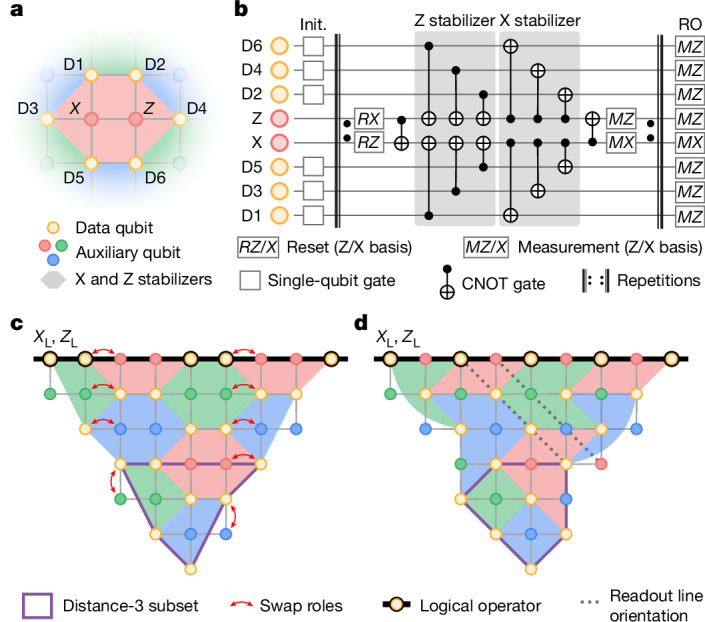
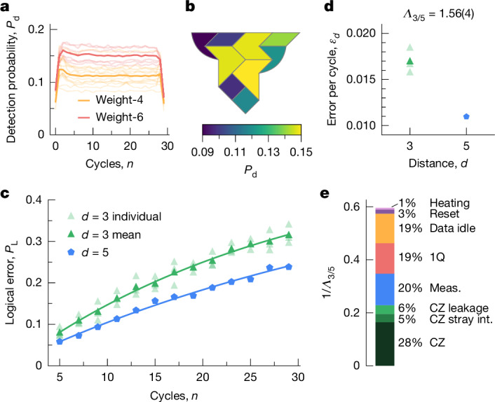
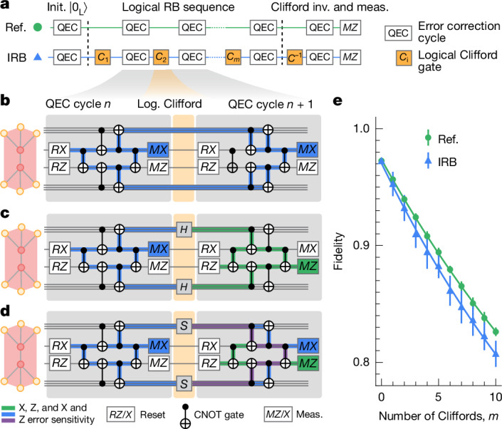
Quantum error correction1-4 is essential for bridging the gap between the error rates of physical devices and the extremely low error rates required for quantum algorithms. Recent error-correction demonstrations on superconducting processors5-8 have focused primarily on the surface code9, which offers a high error threshold but poses limitations for logical operations. The colour code10 enables more efficient logic, but it requires more complex stabilizer measurements and decoding. Measuring these stabilizers in planar architectures such as superconducting qubits is challenging, and realizations of colour codes11-19 have not addressed performance scaling with code size on any platform. Here we present a comprehensive demonstration of the colour code on a superconducting processor8. Scaling the code distance from three to five suppresses logical errors by a factor of Λ3/5 = 1.56(4). Simulations indicate this performance is below the threshold of the colour code, and the colour code may become more efficient than the surface code following modest device improvements. We test transversal Clifford gates with logical randomized benchmarking20 and inject magic states21, a key resource for universal computation, achieving fidelities exceeding 99% with post-selection. Finally, we teleport logical states between colour codes using lattice surgery22. This work establishes the colour code as a compelling research direction to realize fault-tolerant quantum computation on superconducting processors in the near future.


Conflict of interest statement

Competing interests: The authors declare no competing interests.

Figures

Fig. 1
Fig. 1. Superdense colour code.
a, Example tile in the bulk of a red, green and blue hexagonal lattice used for the superdense colour code. The lattice is embedded on a square grid of data qubits (golden circles labelled D1–D6) and X/Z auxiliary qubits (red, green and blue circles), with their connectivity indicated by solid grey lines. b, Superdense syndrome extraction circuit for the tile shown in a (see the main text). c, Distance-5 colour code qubit, with one of the distance-3 qubit subsets outlined in purple. Data qubits included in the logical operators XL and ZL are circled and connected by a solid black line. Red arrows indicate qubit pairs interchanged for the implementation of the colour code on our quantum device. d, Deformed code layout after interchanging the qubits to ensure that each readout line contains only data or auxiliary qubits. The readout lines are oriented diagonally from top left to bottom right (two dashed grey lines).
Fig. 2
Fig. 2. Distance scaling experiment.
a, Detection probability Pd as a function of QEC cycle n for individual stabilizers (faded lines) and their average (solid line) for an X-basis state-preservation experiment in a distance-5 colour code. Weight-6 stabilizers are coloured in red and weight-4 stabilizers are coloured in gold. b, Detection probability for each tile of the distance-5 colour code, averaged over cycles and bases. c, Measured logical error PL for distance-3 (green triangles) and distance-5 (blue pentagons) codes averaged over the X and Z bases. Faded symbols correspond to individual distance-3 subsets. The solid lines, shown for the averaged distance-3 code and the distance-5 code, are fits to PL=ε0×(12×εd)n+1/2, with fitting parameters ε0 and εd. d, Logical error per cycle, εd, compared with code distance, d. Same symbols as in c. e, Relative contributions of different error sources to the error budget for the colour code: CZ errors (CZ); errors from spurious interactions during two-qubit gates (CZ stray int.); leakage errors during two-qubit gates (CZ leakage); measurement errors (Meas.); single-qubit gate error (1Q); data-qubit idle error during measurement and reset of auxiliary qubits (Data idle); reset error (Reset); leakage due to incoherent heating from |1⟩ to |2⟩ (Heating). The relative contributions of the different error channels are indicated.
Fig. 3
Fig. 3. Logical randomized benchmarking.
a, Logical-qubit-level reference (Ref.; green) and interleaved randomized benchmarking (IRB; blue) circuit diagrams, consisting of error correction cycles (QEC), randomly selected Clifford gates (C1, …, Cm), a Clifford recovery gate C−1 and a Z basis measurement (MZ). bd, Simplified circuit diagrams for a tile of the colour code indicating measurements included in an X-stabilizer error-detecting region spanning across two consecutive cycles without logical gate (b), and how it changes on the application of a logical Hadamard gate H (c), or a logical phase gate S (d) between two error correction cycles, see text for details. The green, blue and purple highlighted sections correspond to regions in which the detecting region is sensitive to Z, X and both X and Z errors, respectively. A CNOT gate symbol spanning three qubit wires indicates three consecutive CNOTs between the auxiliary qubit and its neighbouring data qubits. e, Measured fidelity (symbols) and exponential fits (solid lines) for the interleaved (blue) and reference (green) sequences compared with the number of logical Clifford gates m. The data are decoded using the neural-network decoder. Error bars represent the standard deviation of fidelity over 25 random Clifford sequences, each repeated 20,000 times.
Fig. 4
Fig. 4. Arbitrary state injection in a distance-3 colour code.
a, Schematic of a distance-3 colour code. The arbitrary state |ψ⟩ is prepared on the data qubit indicated by a black arrow. The black line indicates the logical operators of the colour code, and the purple ellipses indicate Bell pairs, see the main text. b, Simplified circuit diagram for the state injection. Each line corresponds to one of the data qubits, on which we apply single-qubit Y- and Z-rotations (yellow boxes), Bell pair preparation circuits (purple boxes), a QEC cycle and a measurement in the X, Y or Z basis (MXYZ) for logical state tomography. c, Decoded (semi-transparent circles) and post-selected (solid dots) expectation value of the logical Pauli operators XL (blue), YL (red) and ZL (green) when sweeping the polar angle θ. The solid lines correspond to ideal expectation values. d, Decoded (semi-transparent circles) and post-selected (solid dots) infidelities for the prepared logical state |ψL⟩. e, Magic state |mL⟩ infidelity as a function of rejected data fraction for |AL⟩ (green squares), |HL⟩ (blue diamonds) and |TL⟩ (red triangles), see the main text and Supplementary Information section G. The dashed lines serve as a guide to the eye, and the error bars indicate a 95% bootstrapped confidence interval. Each state is shown on the Bloch sphere by an arrow of the corresponding colour.
Fig. 5
Fig. 5. State teleportation in the colour code using lattice surgery.
a, Simplified circuit diagram to teleport a state |ψL⟩ from logical qubit L1 to a logical qubit L2 using an XX-parity measurement (MXX) realized by lattice surgery, and Pauli frame updates conditioned on the measurement outcomes m1 and m2 performed in post-processing (dashed boxes). b, Space-time block diagram showing the MXX lattice surgery operation, with horizontal cuts displaying the evolution of the stabilizers as a function of the QEC cycles, as detailed in ce. ce, Representation of the active qubits (coloured) and stabilizers before (c) and after (d) the merge operation, and after the split operation (e). The hatched tiles indicate stabilizers in the X basis only, whereas filled tiles indicate both X and Z stabilizers with support on its vertices. The black line indicates the teleported logical operator from L1 to L2, after the Pauli frame update. fi, Measured (colour), simulated (black wireframe) and ideal (dotted grey wireframe) expectation values of the Pauli logical operators of L2 after teleporting state |0L⟩, |1L⟩, |+L⟩ and |−L⟩, respectively. j, Measured (gold bars) and simulated (black wireframe) teleported state fidelity F of the four logical X and Z eigenstates.

References

    1. Shor, P. W. Scheme for reducing decoherence in quantum computer memory. Phys. Rev. A52, R2493–R2496 (1995). - PubMed
    1. Gottesman, D. Stabilizer Codes and Quantum Error Correction. PhD thesis (California Institute of Technology, 1997).
    1. Kitaev, A. Y. Fault-tolerant quantum computation by anyons. Ann. Phys.303, 2–30 (2003).
    1. Terhal, B. M. Quantum error correction for quantum memories. Rev. Mod. Phys.87, 307–346 (2015).
    1. Krinner, S. et al. Realizing repeated quantum error correction in a distance-three surface code. Nature605, 669–674 (2022). - PubMed

LinkOut - more resources