. 2025 May 29;8(1):825.
doi: 10.1038/s42003-025-08239-w.

Cryo-EM structures of HCV E2 glycoprotein bound to neutralizing and non-neutralizing antibodies determined using bivalent Fabs as fiducial markers

Affiliations

Cryo-EM structures of HCV E2 glycoprotein bound to neutralizing and non-neutralizing antibodies determined using bivalent Fabs as fiducial markers

Salman Shahid et al. Commun Biol. .

Abstract

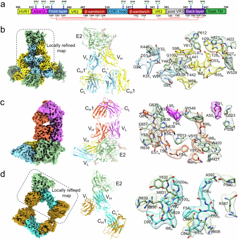
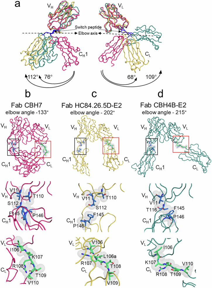
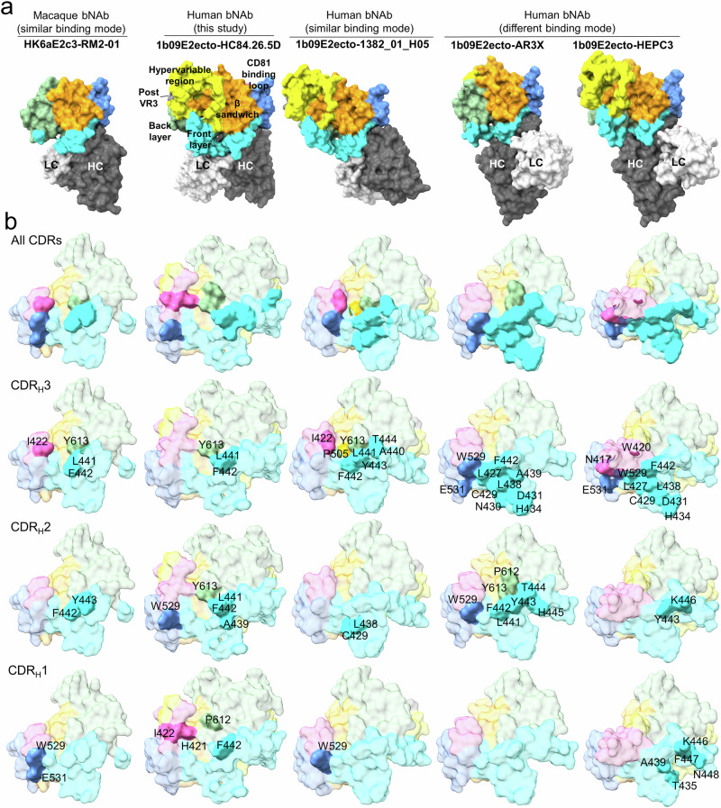
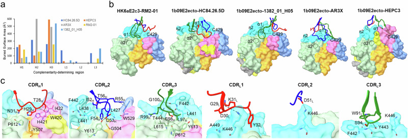
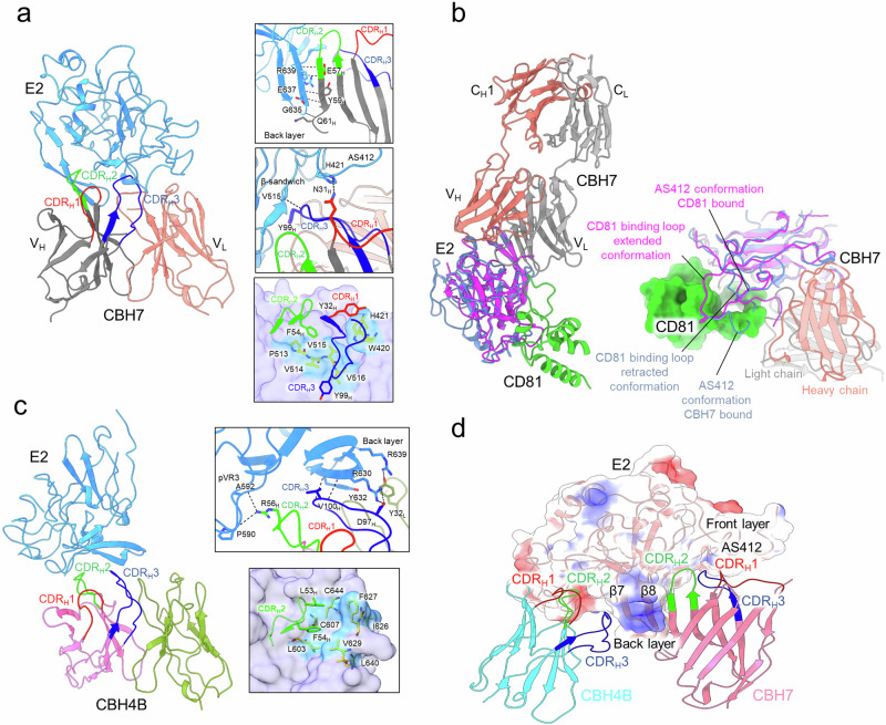
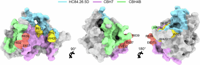
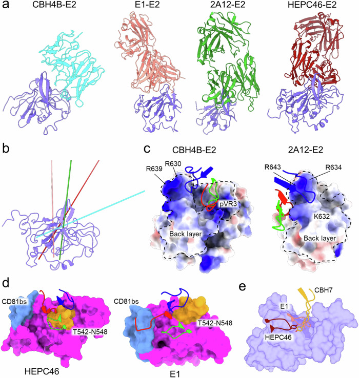
Global elimination of hepatitis C virus (HCV) will require an effective cross-genotype vaccine. The HCV E2 envelope glycoprotein is the main target of neutralizing antibodies but also contains epitopes that elicit non-neutralizing antibodies which may provide protection through Fc effector functions rather than direct neutralization. We determined cryo-EM structures of a broadly neutralizing antibody, a moderately neutralizing antibody, and a non-neutralizing antibody bound to E2 to resolutions of 3.8, 3.3, and 3.7 Å, respectively. Whereas the broadly neutralizing antibody targeted the front layer of E2 and the non-neutralizing antibody targeted the back layer, the moderately neutralizing antibody straddled both front and back layers, and thereby defined a new neutralizing epitope on E2. The small size of complexes between conventional (monovalent) Fabs and E2 (~110 kDa) presented a challenge for cryo-EM. Accordingly, we engineered bivalent versions of E2-specific Fabs that doubled the size of Fab-E2 complexes and conferred highly identifiable shapes to the complexes that facilitated particle selection and orientation for image processing. This study validates bivalent Fabs as new fiducial markers for cryo-EM analysis of small proteins such as HCV E2 and identifies a new target epitope for vaccine development.


Conflict of interest statement

Competing interests: The authors declare no competing interests.

Figures

Fig. 1
Fig. 1. Cryo-EM structures of Fab–E2 complexes.
a Schematic representation of HCV E2 (residues 384–746) colored by structural components, with variable regions (VRs) in yellow, central β-sandwich in red, front layer in blue, CD81 binding loop in cyan, back layer in purple, and stalk and transmembrane region in green. E2 N-linked glycans are indicated. Conserved disulfide bonds are drawn as red dashed lines. b (left) Final reconstructed cryo-EM map of the Fab HC84.26.5D–E2 complex using cryoSPARC. (center) Overall structure of the Fab HC84.26.5D–E2 complex (ribbon diagram). E2 is green; L chain is blue; H chain is yellow. (right) EM map of the interface between E2 and HC84.26.5D. The side chains of interacting residues are shown in stick representation with carbon atoms in green (E2), cyan (L), or yellow (H), nitrogen atoms in blue, and oxygen atoms in red. c (left) Final cryo-EM map of the Fab HC84.26.5D–E2–Fab CBH7 complex. (center) Structure of the Fab HC84.26.5D–E2–Fab CBH7 complex. E2 is green; VL of HC84.26.5D is blue; VH of HC84.26.5D is yellow; L chain of CBH7 is magenta; H chain of CBH7 is orange. (right) EM map of the interface between E2 and CBH7 showing interacting residues. d (left) Final cryo-EM map of the Fab CBH4B–E2 complex. (center) Structure of the Fab CBH4B–E2 complex. E2 is green, L chain is brown; H chain is cyan. (right) EM map of the interface between E2 and CBH4B showing interacting residues.
Fig. 2
Fig. 2. Domain movements and elbow regions in dimeric Fabs.
a (left) Comparison of H chain conformations in unbound monomeric Fab CBH7 (magenta), E2-bound HC84.26.5D (yellow), and E2-bound CBH4B (green). The switch peptide linking VH and CH1 is blue. H chains were superposed through their VH domains. Angles of rotation around the switch peptide with respect to Fab CBH7 are indicated. (right) Comparison of L chain conformations in unbound monomeric Fab CBH7 (magenta), E2-bound HC84.26.5D (yellow), and E2-bound CBH4B (green). The switch peptide linking VL and CL is blue. L chains were superposed through their VL domains. Angles of rotation around the switch peptide with respect to Fab CBH7 are indicated. b (top) Crystal structure of monomeric Fab CBH7 with elbow region between VH and CH1 domains framed in black. The elbow angle is 133°. The elbow region between VL and CL domains is framed in red. (middle) Close-up view of standard ball-and-socket joint between VH and CH1 in Fab CBH7 formed by VH residues Val11, Thr110, and Ser112 (socket) and CH1 residues Phe145 and Pro146 (ball). (bottom) Close-up view of residues forming the elbow region between VL and CL. c (top) Cryo-EM structure of Fab HC84.26.5D in the complex with E2 (not shown) with elbow region between VH and CH1 framed in black. The elbow angle is 202°. The elbow region between VL and CL domains is framed in red. (middle) Close-up view of residues forming ball-and-socket joint in Fab CBH7 but rearranged in the Fab HC84.26.5D–E2 complex. (bottom) Close-up view of residues forming the elbow region between VL and CL. d (top) Cryo-EM structure of Fab CBH4B in the complex with E2 (not shown) with elbow region between VH and CH1 framed in black. The elbow angle is 215°. The elbow region between VL and CL domains is framed in red. (middle) Close-up view of residues forming ball-and-socket joint in Fab CBH7 but rearranged in the Fab CBH4B–E2 complex. (bottom) Close-up view of residues forming the elbow region between VL and CL.
Fig. 3
Fig. 3. Comparison of neutralizing antibodies targeting the E2 front layer.
a Surface representations of HC84.26.5D–E2, AR3X–E2 (PDB code 6URH), HEPC3–E2 (6MEI), 1382_01_H05–E2 (7RFC), and RM2-01–E2 (7JTF) complexes,,,. All structures are superposed on E2 of the HC84.26.5D–E2 complex to illustrate differences in the angle of approach of VH1-69 neutralizing antibodies with respect to E2. The Fab constant domains are not shown for clarity. E2 surfaces are colored by structural components: hypervariable regions, yellow; front layer, cyan; β-sandwich, orange; CD81 binding loop, blue; post-VR3, gray; AS412 region, pink; back layer, green. H and L chains are shown in dark gray and white, respectively. b Epitopes of the front layer-specific neutralizing antibodies are colored on the E2 surface based on their structural components, with interacting residues labeled. Footprints for H chain CDRs are displayed separately.
Fig. 4
Fig. 4. Binding mode and interactions between E2 and CDR loops.
a Comparison of surface areas buried by CDRs of HC84.26.5D, AR3X, HEPC3, 1382_01_H05–E2, and RM2-01,,,. b Surface representations of the HC84.26.5D–E2 and other front layer-binding antibody–E2 structures. E2 surfaces are colored by structural components: hypervariable regions, yellow; front layer, cyan; β-sandwich, orange; CD81 binding loop, blue; post-VR3, gray; back layer, green. The locations of helices α1, α2, and η2 and of Cys429 are marked. The VHCDR1 (red), VHCDR2 (blue), and VHCDR3 (green) loops are mapped onto the E2 surface. c Interactions of VHCDR1–3 and VLCDR1–3 loops of HC84.26.5D with E2. E2 surfaces are colored by structural components: hypervariable regions, yellow; front layer, cyan; β-sandwich, orange; CD81 binding loop, blue; back layer, green. CDR1 (red), CDR2 (blue), and CDR3 (green) loops of VL and VH are shown. Interacting residues are drawn in stick representation and labeled. Hydrogen bonds are indicated by black dashed lines.
Fig. 5
Fig. 5. Structures of CBH7–E2 and CBH4B–E2 complexes.
a Overall structure of the CBH7–E2 complex. E2, blue; H chain, dark gray, L chain, salmon. CH1/CL domains are not shown. VHCDR1, VHCDR2, and VHCDR3 are colored red, green, and blue, respectively. (top inset) β-strand 8 of E2 runs anti-parallel to VHCDR2 and is stabilized by four hydrogen bonds denoted by black dashed lines. Interacting residues are shown in stick representation. (middle inset) Interactions of VHCDR1 and VHCDR3 with E2. (bottom inset) Interactions of VHCDRs with hydrophobic surface on E2. b Superposition of E2 of the CBH7–E2 and CD81–E2 (7MWX) complexes to illustrate the retracted conformation of the AS412 epitope in CBH7-bound E2. Shifting AS412 towards the CD81 binding loop creates steric clashes with CD81. E2 is blue and magenta in the CBH7–E2 and CB81–E2 complexes, respectively; CD81 is green. c Overall structure of the CBH4B–E2 complex. E2, blue; H chain, pink; L chain, green. VHCDR1, VHCDR2, and VHCDR3 are colored red, green, and blue, respectively. (top inset) Hydrogen bond interactions of VHCDRs with the E2 back layer. (bottom inset) Interactions of VHCDRs with hydrophobic surface on E2. d Binding modes of CBH7 and CBH4B on E2 showing β-hairpin formed by β-strands 7 and 8 that separates antigenic domain A from antigenic domain C.
Fig. 6
Fig. 6. Comparison of HC84.26.5D, CBH7, and CBH4B epitopes on E2.
Footprints of HC84.26.5D, CBH7, and CBH4B on E2 are colored according to epitope, with E2 depicted as a gray surface. Residues that interact exclusively with HC84.26.5D are cyan; residues that interact exclusively with CBH7 are pink; residues that interact exclusively with CBH4B are green. Residues interacting with both HC84.26.5D and CBH7 are yellow; residues interacting with both CBH4B and CBH7 are red.
Fig. 7
Fig. 7. Comparison of non-neutralizing antibodies targeting E2.
a Crystal structures of 2A12–E2 (4WEB), E1–E2 (6WO5), and HEPC46–E2 (6MEJ) complexes and cryo-EM structure of CBH7–E2 complex. E1 is a non-neutralizing antibody, not the E1 envelope glycoprotein. The structures are superposed on E2 of the CBH4B–E2 complex to illustrate differences in the orientation of the non-neutralizing antibodies with respect to E2. b Axes of angles of approach of E1 (salmon), 2A12 (green), HEPC46 (maroon), and CBH4B (cyan) over E2 (blue). c Electrostatic surface potential map of E2 in the CBH4B–E2 and 2A12–E2 complexes shows that the VHCDR loops of 2A12 only interact with the back layer, whereas the VHCDR loops of CBH4B also contact pVR3. The back layer and pVR3 regions are outlined with black dashes. The electropositive patch on the back layer of E2 is labeled. VHCDR1, VHCDR2, and VHCDR3 are colored red, green, and blue, respectively. d Surface representation of E2 (magenta) in the HEPC46–E2 and E1–E2 complexes shows positioning of VHCDR loops. In E1, VHCDR1 contacts the CD81 binding loop (light blue), and VHCDR3 interacts with β-sandwich turn T542–N548 (orange), while in HEPC46, all VHCDRs anchor this β-sandwich turn. VHCDR1, VHCDR2, and VHCDR3 are colored red, green, and blue, respectively. e The tips of the VHCDR2 loops of E1 (salmon) and HEPC46 (maroon) interact with the same hydrophobic patch on E2 formed by β-sandwich residues P513–V516.

References

    1. Global Hepatitis Reporthttps://www.globalhep.org/sites/default/files/content/resources/files/20... (2024).
    1. Feeney, E. R. & Chung, R. T. Antiviral treatment of hepatitis C. BMJ348, g3308 (2014). - PMC - PubMed
    1. Rosen, H. R. “HepC, where art thou?”: What are the remaining (fundable) questions in hepatitis C virus research? Hepatology65, 341–349 (2017). - PubMed
    1. Micallef, J. M., Kaldor, J. M. & Dore, G. J. Spontaneous viral clearance following acute hepatitis C infection: a systematic review of longitudinal studies. J. Viral Hepat.13, 34–41 (2006). - PubMed
    1. Osburn, W. O. et al. Clearance of hepatitis C infection is associated with the early appearance of broad neutralizing antibody responses. Hepatology59, 2140–2151 (2014). - PMC - PubMed

MeSH terms

LinkOut - more resources