. 2025 Jun 3;16(1):5149.
doi: 10.1038/s41467-025-60361-9.

Sequential emergence and contraction of epithelial subtypes in the prenatal human choroid plexus revealed by a stem cell model

Affiliations

Sequential emergence and contraction of epithelial subtypes in the prenatal human choroid plexus revealed by a stem cell model

Haley Masters et al. Nat Commun. .

Abstract

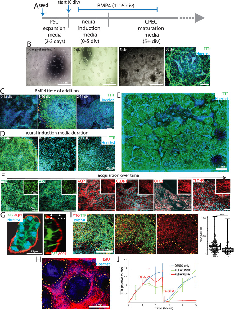
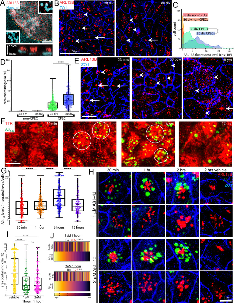
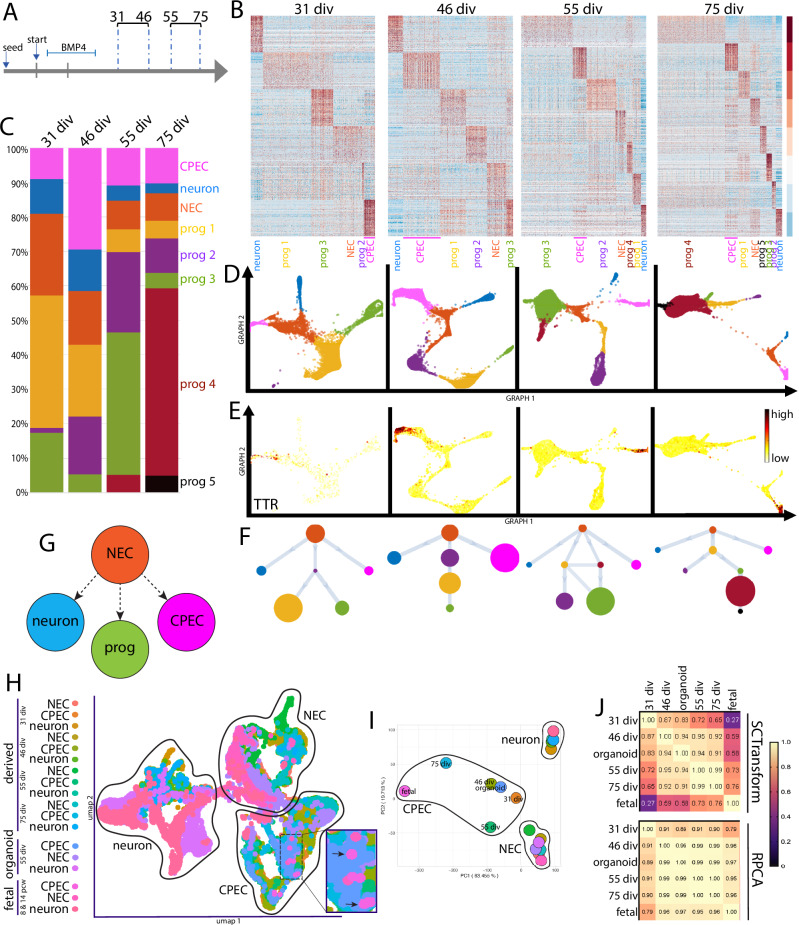
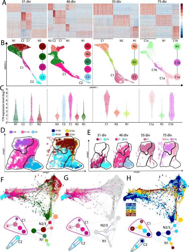
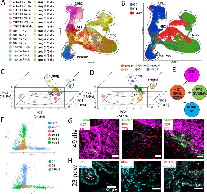
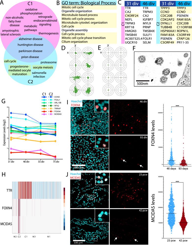
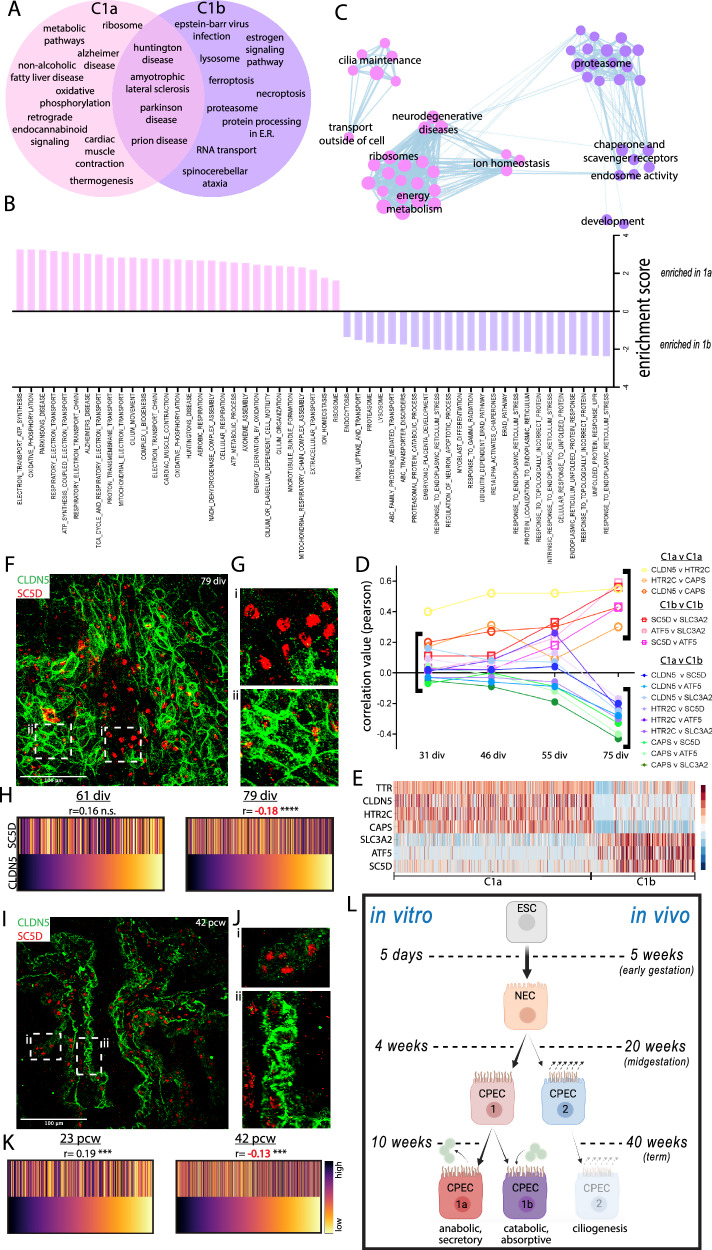
Despite the major roles of choroid plexus epithelial cells (CPECs) in brain homeostasis and repair, their developmental lineage and diversity remain undefined. In simplified differentiations from human pluripotent stem cells, derived CPECs (dCPECs) display canonical properties and dynamic motile multiciliated phenotypes that interact with Aβ uptake. Single dCPEC transcriptomes over time correlate well with human organoid and fetal CPECs, while pseudotemporal and cell cycle analyses highlight the direct CPEC origin from neuroepithelial cells. In addition, time series analyses define metabolic (type 1) and ciliogenic dCPECs (type 2) at early timepoints, followed by type 1 diversification into anabolic-secretory (type 1a) and catabolic-absorptive subtypes (type 1b) as type 2 cells contract. These temporal patterns are then confirmed in independent derivations and mapped to prenatal stages using human tissues. In addition to defining the prenatal lineage of human CPECs, these findings suggest dynamic models of ChP support for the developing human brain.


Conflict of interest statement

Competing interests: The authors declare no competing interests.

Figures

Fig. 1
Fig. 1. dCPEC derivation from H1 ESCs.
Dashed lines demarcate dCPEC islands. A Protocol schematic. Small ESC clumps seeded at low density and subjected only to media changes. BMP4 treatment is 15 days starting at 1 div. B Derivation milestones (phase contrast and epifluorescent TTR ICC) include small low-density ESC colonies after seeding, colony growth to 150–200 um diameter at the start of derivation (0 div), confluent islands by 5 div, and 3D islands by 35 div. C BMP4 time-of-addition (epifluorescent TTR ICC; 20 div). 15 day BMP4 application starting at 1 div, but not 0 or 2 div, leads to strong dCPEC induction. D Neural induction media (NIM) duration (epifluorescent TTR ICC; 25 div). Five days of NIM leads to better dCPEC differentiation than 15 or 25 days. E Example of an efficient derivation (epifluorescent TTR ICC; 45 div). Stitched images of one well in an 8-well chamber slide. F Marker acquisition order (confocal maximal projections; ICC): 35 div for TTR, AE2, AQP1, CLDN1; 50 div for OTX2; 70 div for CLDN5. G Apicobasal polarity (confocal and orthogonal views; ICC 45 div). Apical AQP1+ surfaces face the media, while AE2+ basolateral surfaces abut. H EdU incorporation (40 uM EdU; epifluorescent; 35 div). EdU application from 31–35 div leads to robust labeling of proliferating non-dCPECs (red), but not dCPEC islands. I Mitochondrial activity (confocal maximal projections of 150 nm MTO with TTR-ZO1 ICC; 35 div, ZO1 not shown; box plots designate medians, means “+”, 25th-75th quartiles, and min-max ranges) showing TTR+ dCPECs with significantly higher MTO levels (red) than non-dCPEC neighbors (t-test p < 0.0001****; dCPEC n = 367 cells, non-dCPEC n = 200 cells). J TTR secretion into media following washouts (1 ug/mL BFA; ELISA; means +/- s.d.; 45 div). TTR increases in control wells (blue line) were reduced or blocked acutely by BFA at 2 h (red and green lines), then increased in the absence of BFA after secondary washouts at 5 h, indicating reversibility. Source data provided as a Source Data file. See Statistics and Reproducibility section of Methods for additional information.
Fig. 2
Fig. 2. Dynamic and interacting multiciliated and Aβ1-42 uptake phenotypes.
Images are en face maximal projections except for the in profile image in A. Box plots designate medians, means “+”, 25th-75th quartiles, and min-max ranges. A Multiciliated phenotype (ARL13B ICC; 35 div); dashed line demarcates dCPEC island. Compared to monociliated non-CPECs (inset ii), the multiple apical cilia of dCPECs (inset i and lower panel) are readily apparent even at low magnification. B–D dCPEC cilia mass and dispersion over time (ARL13B-ZO1 ICC). dCPEC cilia are more clustered at 38 div than 80 div (B). Cilia mass per dCPEC increases over time compared to non-dCPECs (C) (one-way ANOVA p = 0.0012, Bonferroni corrected t-test p < 0.0001****; 38-div n = 530, 80-div n = 489). dCPEC cilia-containing surface area also increases over time (D) (one-way ANOVA p < 0.0001, Bonferroni corrected t-test p < 0.0001****; 38-div n = 1189, 80-div n = 923). E CPEC cilia dispersion in vivo (ARL13B-ZO1 whole mount ICC). Clustered cilia (arrows) are more frequent than dispersed cilia (arrowheads) at 23 pcw, but uncommon at 38 pcw and 19 years of age. F, G1-42 uptake and time course (fluorescent Aβ1-42 with TTR-ZO1 ICC; 64 div). Aβ1-42 uptake (green) into TTR+ dCPECs (red) often occurs in circular arrangements (circles in F), with uptake peaking by 6 h, then decreasing by 12 h (G) (one-way ANOVA p < 0.0001, Bonferroni corrected t-tests p < 0.0001****; 30 min n = 419 cells, 1 h n = 415 cells, 6 h n = 492 cells; 12 h n = 300 cells). H–J1-42 uptake and multicilia interaction (fluorescent Aβ1-42 with ARL13B-ZO1 ICC; 64 div). 1 uM or 2 uM Aβ1-42 uptake is robust by 1- or 2 h in dCPECs with clustered cilia (H). After 1 h 1uM or 2 uM Aβ1-42 results in dCPEC populations with more clustered cilia compared to vehicle controls (I) (one-way ANOVA p < 0.0001, Bonferroni corrected t-tests ****p < 0.0001; p = 0.97n.s.; vehicle n = 352, 1 uM n = 100, 2 uM n = 184). Rank-order heatmaps (scale reflects a cells rank) anchored by Aβ1-42 signal show negative correlations between Aβ1-42 levels and cilia clustering after 1 h in 1 uM or 2uM Aβ1-42 (J) (Spearman correlations ****p < 0.0001, **p < 0.01). Source data provided as a Source Data file. See Statistics and Reproducibility section of Methods for additional information.
Fig. 3
Fig. 3. Direct dCPEC origin from tripotent NECs and comparison to human organoid and fetal CPECs.
SoptSC analyses; see Supplementary Fig. 3D–F for Seurat analyses. A Schematic of the four derivation timepoints and their pairings for culturing and scRNA-seq processing. B Heatmaps of top-300 DEGs per cluster. Cell types and color code designated below with dCPECs in pink. Color scale of Z-score of DEGs. C Stacked bar graphs of the percentage of cells in each cluster across the datasets, color coded as in (B). dCPEC percentage is highest at 46 div, then decreases as neural progenitors continue to proliferate and diversify. D GRAPH charts, color coded as in B. At all timepoints, NECs (light brown) have direct branches to dCPECs (pink) and neurons (blue). E GRAPH feature plots highlighting dCPECs (TTR expression). F, G Unsupervised SoptSC pseudotemporal lineages (F) and general lineage model (G). NECs (light brown) have direct branches to dCPECs (pink) and neurons (blue) at all timepoints. NEC relationships to progenitors (“prog”) are more varied. H UMAP of dCPECs, NECs, and neurons aggregated with organoid and fetal CPECs (SCTransform-corrected). CPECs from all sources form a cluster. Fetal CPECs cluster with older dCPECs (inset). I PCA of clusters, color coded as in (H). The 75-div dCPEC cluster approaches the fetal CPEC cluster, while organoid CPECs display intermediate differentiation. J Pearson correlation tables (color scale ranges from r = 0 to r = 1) using two batch correction methods. With SCTransform (top), CPECs display more differences. The dCPECs progress in an orderly temporal fashion towards the organoid, then fetal CPECs. RPCA correction (bottom) highlights CPEC similarities regardless of source. See Supplementary Fig. 4C–D for complete correlation tables.
Fig. 4
Fig. 4. SoptSC and STITCH analyses across timepoints suggest a branching dCPEC lineage tree.
A Heatmaps of the top-300 DEGs for dCPECs (“C”) and NECs (“N”) suggest two dCPEC subtypes at 3 of the 4 timepoints, but only one cluster at 55 div. Color scale of Z-score of DEGs. B SoptSC GRAPH charts and lineage relationships coded by subtype. NECs are more similar to C1 than C2 cells. See Supplementary Fig. 5C for pseudotemporal color coding. C Violin plots (with median and quartiles) of TTR expression in the cells of each cluster across the datasets, which increases in dCPECs over time with C1 > C2 and C1a > C1b. Every dot represents a cell. D UMAPs of aggregated dCPECs, color coded and encircled for simplified subtype groupings (left) or timepoint (right). C2 cells (lower right) are mainly present early, but also at later timepoints, while C1 cells shift over time. E UMAPs of dCPECs from individual timepoints, color coded for dCPEC subtype as in B. As C2 cells contract, C1 cells adopt a “hybrid” C1a-C1b profile at 55 div before specifying into C1a and C1b subtypes by 75 div. FH STITCH dot plots (upper) and lineage trees (lower), color coded for all subtypes (F), dCPEC subtypes only (G), or timepoint (H). The dCPECs cluster towards the left of the roughly-triangular dot plots, with NECs at the other two corners. Each corner has cells from all four timepoints (H). C1 (pink-purple) and C2 cells (blues) belong to distinct lineages from the outset. The C2 lineage displays transience, while the C1 lineage evolves and diversifies. Small 55-div and 75-div C2 “clusters” were manually added to the lineage trees to indicate their presence in low numbers at these timepoints.
Fig. 5
Fig. 5. Cell cycle analyses highlight NEC tripotency and reveal a distinctive ‘neural G0’ dCPEC signature.
Human ‘neural G0’ transcriptomic analysis (A–F) with confocal maximal projections in derived cells (G) and 23 pcw tissue (H). A, B UMAP of all cells across timepoints, color coded for subtype and timepoint (A) or ‘neural G0’ phase (G0, G1, G2M/S), with major progeny classes encircled. The tripotent NEC progeny class structure is again evident (A). Across timepoints, dCPECs and neurons have predominant G0 signatures (blue), while NECs and progenitors are predominantly in G1 or G2M/S. C, D 3D ‘neural G0’ PCA plots of subtype clusters across timepoints, color coded for subtype as in A (C) or for predominant cell cycle phase(s) (D); see Supplementary Fig. 7A, B for details. The three branches of NEC progeny are evident from neural G0 analysis alone (C). While dCPECs and neurons are principally G0 cells (orange), neural G0 analysis also distinguishes dCPECs from neurons (D). E Lineage model for tripotent NECs (Fig. 3G) with predominant cell cycle signatures added. F 2D ‘neural G0’ PCA scatterplot of all cells from the earliest timepoint (31 div), color coded for cell type (upper) or cell cycle phase (lower). NEC tripotency and dCPEC-neuron distinction are evident by 31 div. G KI67 status of dCPECs at an intermediate timepoint in vitro (TTR-FOXN4-MAP2-KI67 ICC; 49 div). KI67 (red) labels cells outside of dCPEC islands (middle panel), but not dCPECs (purple) or neurons (green in right panel). FOXN4 + C2 cells (arrow in left panel) also lack KI67 expression. H KI67 status of CPECs at midgestation in vivo (MCIDAS-KI67 IHC; 23 pcw); middle and right panels are immediately adjacent. Nuclear KI67 is present in some stromal cells (arrow in left panel), but not in CPECs, including MCIDAS + C2 cells (arrowheads in right panel). See Fig. 6 for C2 marker studies using FOXN4 and MCIDAS.
Fig. 6
Fig. 6. Early type 1 and type 2 CPECs, with later type 2 contraction.
A, B Venn diagram of all enriched KEGG pathways (p < 0.05 with Bonferroni correction) (A) and top-10 GO terms for C2 cells (B) based on top-300 DEGs of C1 and C2 clusters at 31 div. Microtubule/ciliogenesis-associated terms are highlighted. C1 (pink) is enriched for metabolic and energy-related pathways, while C2 (blue) is enriched for microtubule/ciliogenesis terms. C1 and C2 subtypes share enrichment for neurodegenerative disease pathways. C Top-10 DEGs for C1 (left) and C2 subtypes (right) at 31 and 46 div, with microtubule/ciliogenesis-associated genes highlighted. C2 cells express ciliogenesis genes at particularly high levels. D, E Live-image cilia tracking at 42 div (D) and 110 div (E) of one cilia tip every 100 frames (0.5 s) over 50 s (100 dots). Variable motility patterns are observed at 42 div, but not at 110 div (target circles, 4.14 um in diameter). See also Supplementary Movies 1–3. F Transmission electron micrograph from a 40-div dCPEC culture. Five axonemes contain the central pair of singlet microtubules and “9 + 2” arrangement characteristic of motile cilia. G Gene expression levels (log2) of seven master regulators of ciliogenesis. C2 cells (dashed lines) express higher levels than C1 cells (solid lines), particularly FOXN4 (red) and MCIDAS (purple). H Heatmap of NEC and dCPEC subtypes at 46 div. FOXN4 and MCIDAS distinguish C2 from C1 cells and NECs. Color scale of Z-score of DEGs. I C2 contraction in vitro (FOXN4 ICC maximal projections and violin plots with medians; 46 and 93 div). FOXN4 fractional positivity and expression levels decrease between 46 and 93 div (t-test p < 0.0001****; n = 300 cells each), although C2 cells are detectable at 93 div (arrows). J C2 contraction in vivo (MCIDAS IHC maximal projections and violin plots with medians; 23 and 42 pcw). Like FOXN4 in vitro, MCIDAS fractional positivity and expression levels decrease between 23 and 42 pcw (t-test ****p < 0.0001; 23 pcw n = 799 cells, 42 pcw n = 1504 cells), although C2 cells are detectable at 42 pcw (arrows). Source data provided as a Source Data file. See Statistics and Reproducibility section of Methods for additional information.
Fig. 7
Fig. 7. Late type 1a and type 1b CPECs with prenatal lineage summary.
A Venn diagram of significantly-enriched KEGG pathways (p < 0.05 with Bonferroni correction) based on top-300 DEGs of C1a and C1b cells at 75 div. C1b cells (purple) are distinctively enriched for catabolic processes, while C1a cells (pink) share many metabolic and energy-associated pathways enriched in 31-div C1 cells (Fig. 6A). See Supplementary Fig. 9A and Supplementary Data 1 for directed GSEA analyses of anabolic-secretory and catabolic-absorptive pathways. B Enriched GSEA terms for C1a (pink) and C1b cells (purple) using filtered genes (see Methods) expressed by >25% of cells. C Annotated GSEA theme plot illustrating C1a and C1b pathway enrichments. D Pearson correlations among (red-yellow) or between (green-violet) C1a and C1b marker gene pairs. Note the increase in some correlations at 55 div before their strong anti-correlations by 75 div. E 75 div heatmap of C1a and C1b marker genes used in panels D–K and Supplementary Fig. 9C–K. Color scale of Z-score of DEGs. F–H C1a-C1b specification in vitro (CLDN5-SC5D ICC maximal projections with magnified insets and rank-order heatmaps with Spearman correlations; 61 and 79 div). Unlike CLDN5-SC5D coexpression at 61 div (Supplementary Fig. 9F), discrete regions of CLDN5hi-SC5Dlo (C1a) and SC5Dhi-CLDN5lo (C1b) cells are evident by 79 div (F, G). A trend towards positive CLDN5-SC5D correlation at 61 div (p = 0.2n.s.; n = 150 cells) becomes significantly negative by 79 div (p < 0.0001****; n = 584 cells) (H). I–K C1a-C1b specification in vivo (CLDN5-SC5D IHC maximal projections with magnified insets and rank-order heatmaps with Spearman correlations; 23 and 42 pcw). Similar to in vitro, discrete regions of CLDN5hi-SC5Dlo (C1a) and SC5Dhi-CLDN5lo (C1b) cells are evident by 42 pcw. At 23 pcw, CLDN5-SC5D correlation is significantly positive (p < 0.001***; n = 323 cells) before becoming significantly negative by 42 pcw (p < 0.001***; n = 812 cells). Color scale of fluorescence levels for CLDN5 and SC5D. L Summary of the CPEC lineage tree with in vitro and in vivo timepoints. Source data provided as a Source Data file. See Statistics and Reproducibility section of Methods for additional information.

Update of

Similar articles

Cited by

References

    1. Lun, M. P., Monuki, E. S. & Lehtinen, K. Development and functions of the choroid plexus–cerebrospinal fluid system. Nat. Rev. Neurosci.16, 445–457 (2015). - PMC - PubMed
    1. Faraci, F. M., Mayhan, W. G. & Heistad, D. D. Effect of serotonin on blood flow to the choroid plexus. Brain Res.478, 121–126 (1989). - PubMed
    1. Faraci, F. M., Baumbach, G. L. & Heistad, D. D. Cerebral circulation: humoral regulation and effects of chronic hypertension. J. Am. Soc. Nephrol.1, 53–57 (1990). - PubMed
    1. Hablitz, L. M. & Nedergaard, M. The glymphatic system: a novel component of fundamental neurobiology. J. Neurosci.41, 7698–7711 (2021). - PMC - PubMed
    1. Simon, M. J. & Iliff, J. J. Regulation of cerebrospinal fluid flow in neurodegenerative, neurovascular and neuroinflammatory disease. Biochimica. Biophysica. Acta Mol. Basis Dis.1862, 442–451 (2016). - PMC - PubMed

LinkOut - more resources