

Effects of Plate-Bone Contact on Bridge Plate Fracture Fixation Biomechanics: Computational, Experimental, and Analytical Modeling
- PMID: 40483596
- PMCID: PMC12329631
- DOI: 10.1002/jor.26114
Effects of Plate-Bone Contact on Bridge Plate Fracture Fixation Biomechanics: Computational, Experimental, and Analytical Modeling
Abstract
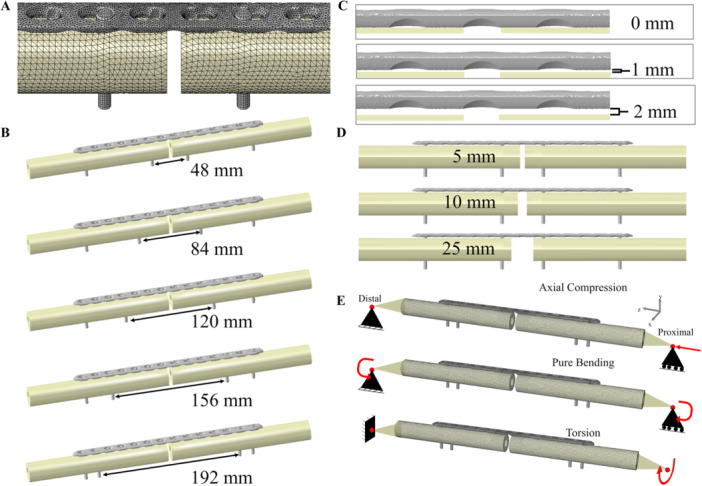
Bridge plating is commonly used for internal fixation of comminuted fractures. The inner working length between screws has been established as a key parameter controlling postoperative biomechanical stability. However, plate-bone contact may affect these biomechanics in complex ways, and the offset between the plate and bone is variable across surgeries. The objective of this study was to examine the effects of construct and loading parameters on interfragmentary motion and maximum plate stress of bridge plating constructs. Finite element models were developed with variations in inner working length, plate-bone offset, fracture gap size, and loading type and magnitudes. Experiments with synthetic bones were conducted in parallel to support model credibility. Analytical models were also developed based on beam bending and torsion of the plate, assuming rigidity outside the inner working length. Finite element and experimental results of axial and torsional loading scenarios without plate-bone contact confirmed linear relationships between inner working length and interfragmentary motion. Analytical predictions of interfragmentary motion showed very good agreement with the finite element simulations in these scenarios. Conversely, in cases with plate-bone contact, a shorter effective working length was formed, and results were dependent on additional variables such as fracture gap. The study shows how the mechanics of bridge plating can be understood and predicted based on beam theory up to the point of plate-bone contact, and how interfragmentary motions and maximum plate stresses are influenced by the interaction of surgical variables in the presence of plate-bone contact.
Keywords: beam bending model; biomechanics; bridge plating; bridge span; finite element analysis; fracture fixation; fracture plate; interfragmentary motion; plate clearance; plate working length.
© 2025 The Author(s). Journal of Orthopaedic Research® published by Wiley Periodicals LLC on behalf of Orthopaedic Research Society.
Conflict of interest statement
J. Spence Reid is a product development consultant with Depuy Synthes, a product development consultant with Osteocentric, and a stockholder with ROMtech. The other authors declare no conflicts of interest.
Figures


References
-
- Lujan T. J., Henderson C. E., Madey S. M., Fitzpatrick D. C., Marsh J. L., and Bottlang M., “Locked Plating of Distal Femur Fractures Leads to Inconsistent and Asymmetric Callus Formation,” Journal of Orthopaedic Trauma 24 (2010): 156–162. - PubMed
-
- Ring D., Kloen P., Kadzielski J., Helfet D., and Jupiter J. B., “Locking Compression Plates for Osteoporotic Nonunions of the Diaphyseal Humerus,” Clinical Orthopaedics and Related Research 425 (2004): 50–54. - PubMed
-
- Ramotowski W. and Granowski R., “Zespol: An Original Method of Stable Osteosynthesis,” Clinical Orthopaedics and Related Research 272 (1991): 67–75. - PubMed
-
- Südkamp N., Bayer J., Hepp P., et al., “Open Reduction and Internal Fixation of Proximal Humeral Fractures With Use of the Locking Proximal Humerus Plate. Results of a Prospective, Multicenter, Observational Study,” Journal of Bone and Joint Surgery–American Volume 91 (2009): 1320–1328. - PubMed
-
- Fares A. B., Childs B. R., Polmear M. M., Clark D. M., Nesti L. J., and Dunn J. C., “Dorsal Bridge Plate for Distal Radius Fractures: A Systematic Review,” Journal of Hand Surgery 46 (2021): 627.e1–627.e8. - PubMed
MeSH terms
Grants and funding
LinkOut - more resources
Full Text Sources
Miscellaneous
