. 2025 Apr 26;22(2):e220010.
doi: 10.2142/biophysico.bppb-v22.0010. eCollection 2025.

A low-cost electric micromanipulator and its application to single-cell electroporation

Affiliations

A low-cost electric micromanipulator and its application to single-cell electroporation

Kazuma Shimizu et al. Biophys Physicobiol. .

Abstract

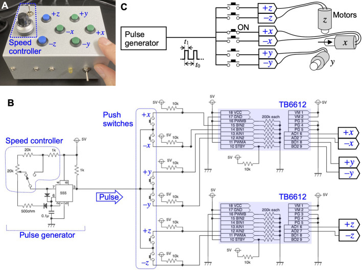
Micromanipulation techniques are essential in studies of cell function, both for single cells and for cell collectives. Various types of micromanipulators are now commercially available. Hydraulic micromanipulators have the advantage of analogue operation, allowing the user to move the glass microneedle in direct response to their own hand movements. However, they require regular maintenance to maintain their performance. On the other hand, some electric micromanipulators can operate in minute steps of several hundred nanometers, but they are expensive. This paper describes our assembly of a low-cost electric micromanipulator. The device consists of three commercially available stages, three linear DC motors to drive them, and a lab-made control circuit. Using this device, we were able to direct a glass microneedle to cut an MDCK cell sheet. We also manipulated an aspiration pipette to aspirate a portion of a Dictyostelium cell. In addition, we were able to gently touch the tip of an electroporation pipette to the surface of a single target cell in a sheet of fish epidermal keratocytes and load FITC into the cell. Our device can be assembled at one-fourth the cost of commercially available hydraulic micromanipulators. This could make it easier, both economically and technically, to add micromanipulators to all of a laboratory's microscopes.

Keywords: Dictyostelium; MDCK cells; keratocytes; microinjection; micromanipulation.


Conflict of interest statement

The authors declare no competing interests.

Figures

Figure 1
Figure 1
Overview of the moving part of the new electric micromanipulator. (A) Photographs of the moving part located on the right side of the inverted microscope stage from the front (Front), top (Top) and right (Right) directions, respectively. (B) Schematic diagrams corresponding to each of the three photographs in (A). The x, y and z in (A) and (B): DC motors.
Figure 2
Figure 2
Overview of the operator part of the new electric micromanipulator. (A) Lab-made operation box. (B) Electric circuit for motor control in box (A). (C) Simplified schematic diagram of (B). The voltage pulses output from the pulse generator are transmitted to the motor whose button is pressed (ex. +x, ON). The motor is then driven (arrow). The cycle of the pulses, t0, is fixed at 3.9 ms. The motion speed of the motors is a function of the duty ratio (t1/t0), which is continuously adjustable from 0.012 to 0.49 using the dial or set at 0.98 using the toggle switch ((A) and (B), Speed controller).
Figure 3
Figure 3
Overview of the single-cell electroporator. (A) The electric circuit. (B) The case that encloses the circuit shown in (A). (C) Simplified schematic diagram of (A). V1 and V2: power supplies, R1: pipette resistor, R2: gap resistor between the pipette tip and the cell surface. SW1: switch. SW1 is equivalent to SW0 in (A). In all the experiments in this report, V1 was set to –1 V. When the pipette tip touches the cell surface (Middle, white arrow), R2 increases and the current decreases (Middle, blue arrows). The current drop is confirmed on the oscilloscope and SW1 is operated (Right, white arrow). The supply voltage becomes V1+V2 and the substances in the pipette are loaded.
Figure 4
Figure 4
Testing the new electric micromanipulator. (A and B) Checking the motion speed averaged over 30 ms. An aspiration pipette was held by the micromanipulator (insets), and the speeds in the positive and negative directions were compared in both the x- and y-directions. The cycle of PWM control pulses (t0 in (A)) was set at 3.9 ms, and the duty ratio (t1/t0) was varied from 0.012 to 0.49 or fixed at 0.98. (C–L) High time resolution (1 ms) motion analysis. PWM control pulses with duty ratios of 0.13 (C), 0.25 (D), or 0.49 (E) were applied. The speeds of the pipettes in the ±x (F–H) and ±y (I–K) directions in response to the pulse input (C–E) and their mean values over 80 ms (L) are shown. Error bars in (A), (B) and (F–L) represent SEM. The p values in (L) were calculated using one-way ANOVA.
Figure 5
Figure 5
Practical use of the new electric micromanipulator. (A) Cutting of MDCK cell sheets. The cell sheet was cut into a square by manipulating a glass microneedle (yellow arrows). (B) The cell sheet after having been cut into a square (A). Some of the cells at the edge of the square fragment began to move (yellow arrowheads), similar to the typical behavior of MDCK cells in a scratch wound assay. The result is representative of nine experiments. (C) Micropipette aspiration. Accumulation of GFP-myosin II was observed at the cortex in the portions of the Dictyostelium cell deformed by aspiration (yellow arrows). After the negative pressure had been released, the apparently undamaged cells resumed migration. The result is representative of nine experiments.
Figure 6
Figure 6
Use of the new electric micromanipulator for single-cell electroporation. (A) Micromanipulation of the electroporation pipette before and after the electroporation of a single leader cell in a fish keratocyte sheet. The tip of the pipette containing FITC is shown (blue arrows). The pipette tip is moved horizontally to just above the target cell (square) (0–5.9 s). The pipette is lowered to bring it into contact with the cell surface (20 s). After electroporation at –5 V for 500 ms, the pipette is lifted (31.5 s) and moved horizontally away from the cell (33 s). (B) Enlarged images of the square in 0 s in A. The pipette tip (blue arrows) is lowered by –z operation of the micromanipulator. Dotted line: outline of the targeted cell. (C) Current drop at 20 s caused by the pipette touching the cell surface, recorded simultaneously with (A). (D) A keratocyte sheet. FITC was loaded into one leader cell (yellow asterisk). Shown in (A–D) are representative of thirteen experiments. (E) MDCK cells loaded with FITC at different voltages for 500 ms. Three cells (yellow asterisks) were loaded at each voltage. (F) Average fluorescence intensity of the cytoplasm of the three cells at each voltage.

References

    1. Hiramoto, Y. V-2 Micromanipulation. Cell Struct. Funct. 9, s139–s144 (1984). https://doi.org/10.1247/csf.9.supplement_s139 - PubMed
    1. Korzh, V., Strähle, U.. Marshall Barber and the century of microinjection: from cloning of bacteria to cloning of everything. Differentiation 70, 221–226 (2002). https://doi.org/10.1046/j.1432-0436.2002.700601.x - PubMed
    1. Chambers, R. New apparatus and methods for the dissection and injection of living cells. Anat. Rec. 24, 1–19 (1922). https://doi.org/10.1002/ar.1090240102
    1. Hiramoto, Y. Cell division without mitotic apparatus in sea urchin eggs. Exp. Cell Res. 11, 630–636 (1956). https://doi.org/10.1016/0014-4827(56)90171-9 - PubMed
    1. Hiramoto, Y. Further studies on cell division without mitotic apparatus in sea urchin eggs. J. Cell Biol. 25, 161–167 (1965). https://doi.org/10.1083/jcb.25.1.161 - PMC - PubMed