. 2025 May 28;17(11):1502.
doi: 10.3390/polym17111502.

Conductivity of Filled Diblock Copolymer Systems: Identifying the Main Influencing Factors

Affiliations

Conductivity of Filled Diblock Copolymer Systems: Identifying the Main Influencing Factors

A I Chervanyov. Polymers (Basel). .

Abstract

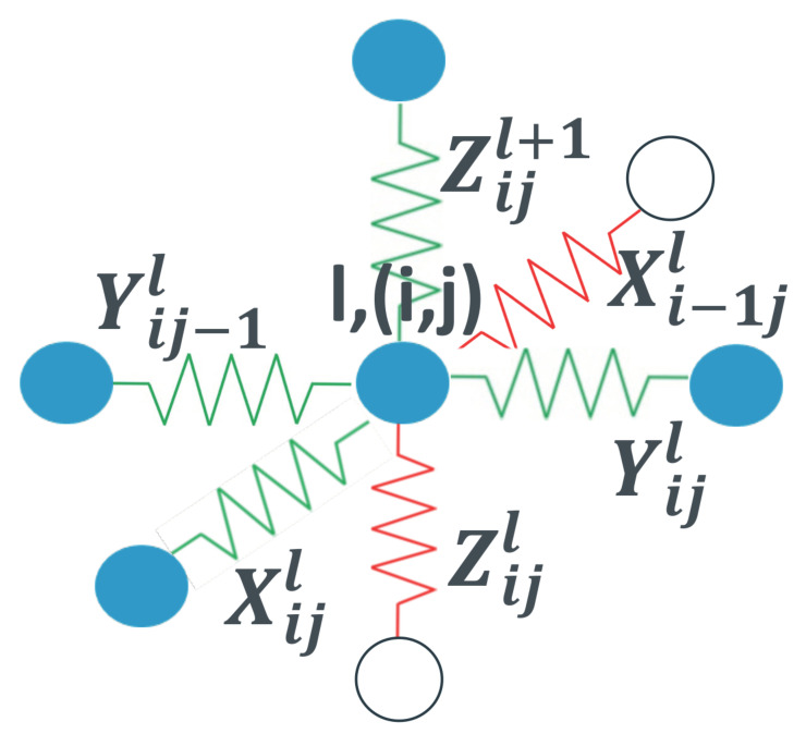
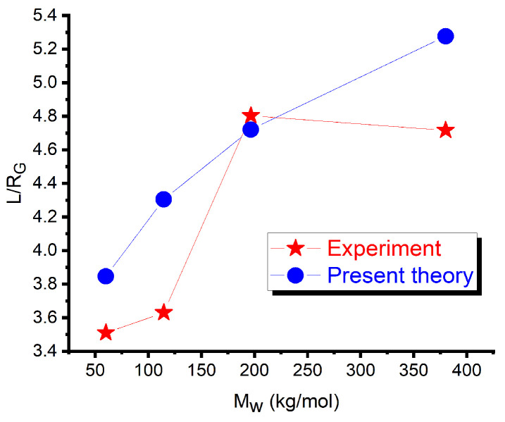
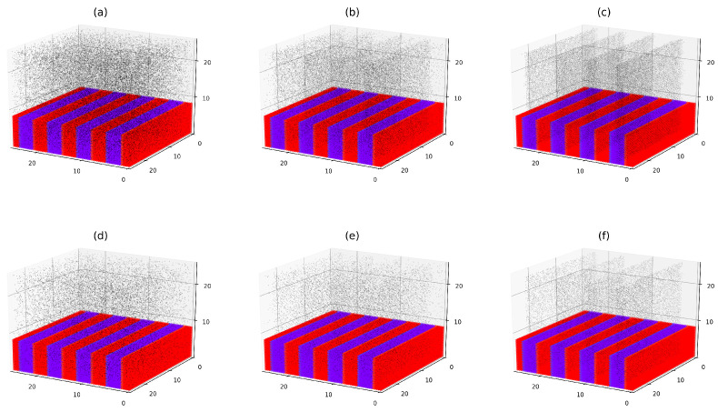
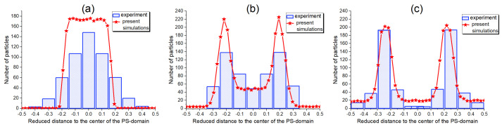
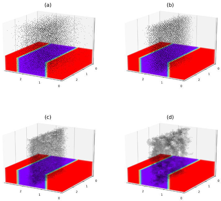
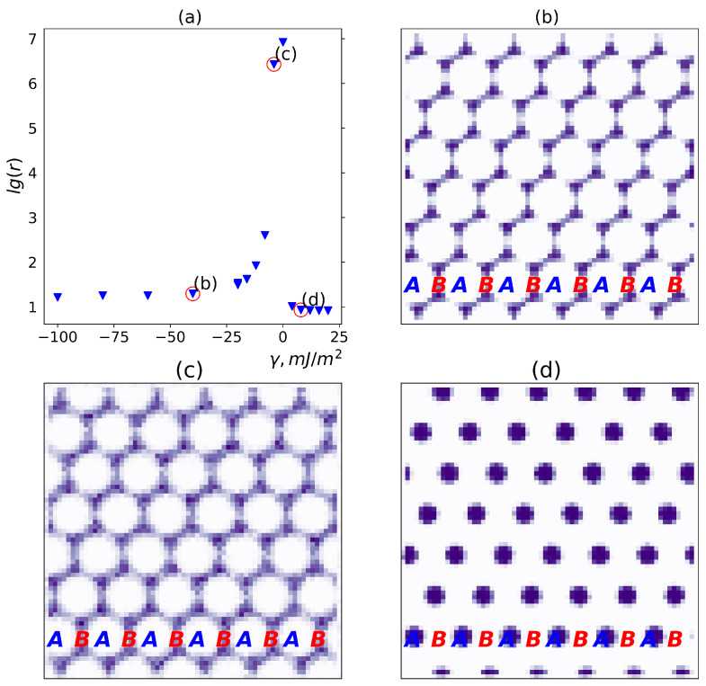
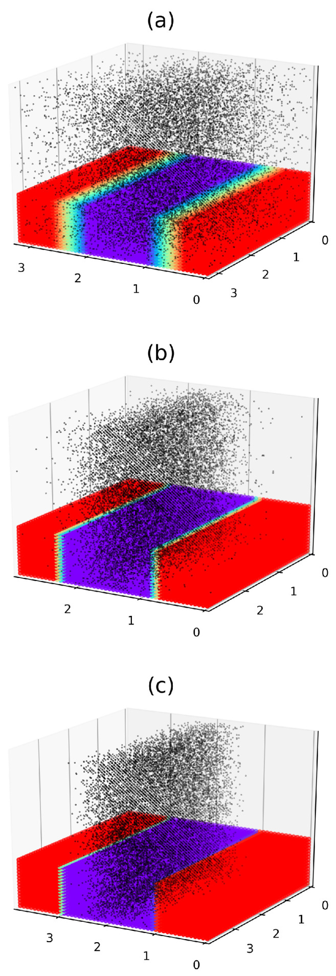
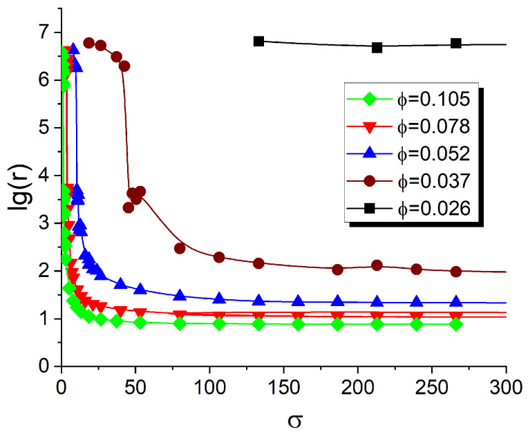
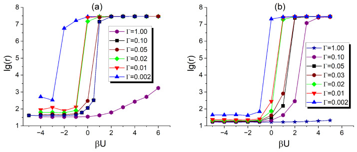
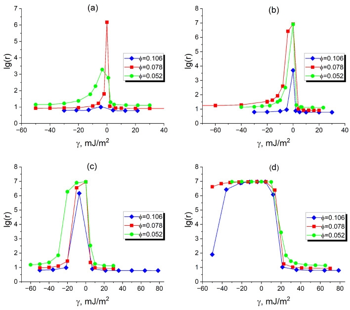
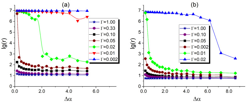
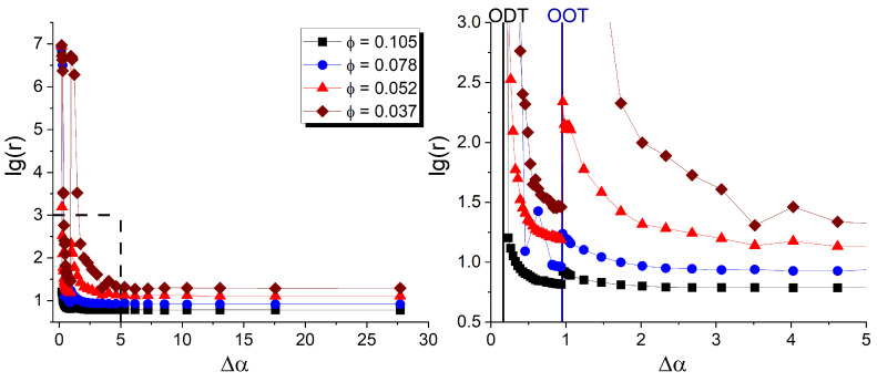
By developing and making use of the multi-scale theoretical approach, we identify the main factors that affect the conductivity of a composite composed of a diblock copolymer (DBC) system and conductive particles. This approach relies on the consistent phase-field model of DBC, Monte-Carlo simulations of the filler localization in DBC, and the resistor network model that mimics the conductive filler network formed in DBC. Based on the described approach, we thoroughly explore the relation among the morphological state of the microphase-separated DBC, localization of fillers in DBC, and the electrical response of the composite. Good agreement with experimental results confirms the accuracy of our theoretical predictions regarding the localization of fillers in the DBC microphases. The main factors affecting the composite conductivity are found to be: (i) affinities of fillers for copolymer blocks; (ii) degree of the segregation of a host DBC system, driven by external stimuli; (iii) geometry of the microphases formed in the microphase-separated DBC; and (iv) interactions between fillers. The conductor-insulator transition in the filler network is found to be caused by the order-disorder transition in the symmetric DBC. The order-order transition between the ordered lamellae and cylindrical microphases of asymmetric DBC causes a spike in the composite conductivity.

Keywords: conduction; diblock copolymers; fillers.


Conflict of interest statement

The author declares no conflict of interest. The funders had no role in the design of the study; in the collection, analyses, or interpretation of data; in the writing of the manuscript; or in the decision to publish the results.

Figures

Figure 1
Figure 1
Unit cell of the constructed random resistor network. See the explanation and notations in the text.
Figure 2
Figure 2
Comparison of the reduced lamella period calculated by numerically solving the phase-field Equation (4) with Δw=0 against the experiment in [36]. All lengths are measured in the gyration radii of the DBC derived from their molecular weights assuming the monomer length of 0.5 nm. Adapted with permission from [27], APS, 2020.
Figure 3
Figure 3
Effect of the difference in affinities of fillers for dissimilar copolymer blocks on their localization in the DBC lamellae. Filler volume fractions ϕ for plots shown in the upper and lower panels are set to 0.078 and 0.037, respectively. For each ϕ, several cases corresponding to selected values of affinity contrast, σ, are shown: ϕ=0.078: (a) σ=0.0, (b) σ=5.3, (c) σ=133.1; ϕ=0.037: (d) σ=0.0, (e) σ=5.3, (f) σ=133.1. Black dots represent the centers of the filler particles. The upper part of the images of the host DBC is cut off to make the localization of fillers inside the DBC system visible. The selective A phase, which has a larger affinity for polymers, is shown in red, and the B phase is shown in violet. All lengths are measured in RG.
Figure 4
Figure 4
The localization of gold fillers in the lamellar domains of the DBC PS-b-P2VP for several selected values of the surface fraction FPS of the PS-ligands: (a) 0.92, (b) 0.90, and (c) 0.80. The interface boundaries of the PS domain are located at 0.25 and 0.25. The experimental histograms in blue show the filler localization in the cross section of the lamellar domains, as obtained in [52] from transmission electron microscopy micrographs. The line-symbol curves in red show the simulation results for the values of the affinity parameter g, evaluated for the corresponding FPS. See the explanation in the text. Adapted with permission from [27], APS, 2020.
Figure 5
Figure 5
Localization of fillers, interacting through the potential U, in the lamellae formed by the microphase-separated DBC system. The energy of the inter-particle interaction U is set to: (a) 10.0kT; (b) 1.0kT; (c) 1.0kT; (d) 10.0kT. The reduced segregation parameter Δα is set to 12.1. Black dots represent the centers of the filler particles. The upper part of the image of the host DBC matrix is cut off to make the distribution of fillers inside the DBC system visible. The selective A phase, which has a larger affinity for fillers, is shown in red, while the B phase is shown in violet. All lengths are measured in RG. The radius of the fillers is 0.07RG. The volume fraction of fillers is 0.052.
Figure 6
Figure 6
Effect of difference γ between affinities of fillers for dissimilar copolymer blocks on the conductivity of the microphase-separated asymmetric DBC system (f=0.45) and the localization of fillers in this system. The reduced segregation Δα, volume fraction of fillers ϕ, and reduced inter-filler interaction energy βU are set to 32.6, 0.078, and 1.0, respectively. (a) Conductivity as a function of γ. Red circles highlight the points corresponding to the cases of the respective γ values illustrated in subplots (bd). (bd) Localization of fillers for selected values of γ: (b) γ=40mJ/m2, (c) γ=4mJ/m2, (d) γ=8mJ/m2. See the explanation in the text.
Figure 7
Figure 7
Effect of changing the degree of segregation of the DBC blocks, quantified by the reduced segregation parameter Δα, on the localization of fillers in the microphase-separated DBC system. Δα is set to: (a) 0.2; (b) 1.5; (c) 8.6. The centers of the filler particles are represented by black dots. The upper part of the image of the host DBC matrix is cut off to make the localization of fillers inside the DBC system visible. The selective A phase, which has a larger affinity for fillers, is shown in red, and the B phase is shown in violet. All lengths are measured in RG, so the radius of the fillers is 0.07. The energy of the inter-particle interaction U is set to 0.1kT. The volume fraction of particles is 0.052.
Figure 8
Figure 8
Effect of the difference between the affinities of fillers for dissimilar copolymer blocks quantified by σ on the resistivity of the filled DBC for several selected volume fractions ϕ of fillers.
Figure 9
Figure 9
Effect of the interaction between fillers on the resistivity of the filled DBC system for several selected values of the affinity parameter Γ and filler volume fraction ϕ: (a) ϕ=0.052. (b) ϕ=0.105. See the explanation in the text.
Figure 10
Figure 10
Reduced resistivity of the microphase-separated asymmetric DBC system (f=0.45), which assumes cylindrical morphology, as a function of the filler affinity contrast for dissimilar copolymer blocks, γ, for selected inter-filler interaction energies, U: (a) βU=5.0; (b) βU=1.0; (c) βU=1.0; (d) βU=5.0. Reduced segregation is set to Δα=2.0. The volume fraction of fillers, ϕ, is set equal to the values shown in the legend. See the explanation in the text.
Figure 11
Figure 11
Reduced resistivity of the microphase-separated symmetric (f=0.5) DBC system as a function of the reduced segregation parameter Δα for several selected values of the affinity parameter Γ and filler volume fraction ϕ: (a) ϕ=0.052. (b) ϕ=0.105. See the explanation in the text.
Figure 12
Figure 12
Left panel: Reduced resistivity of the microphase-separated asymmetric (f=0.45) DBC system as a function of the reduced segregation parameter Δα for several selected values of the filler volume fractions ϕ. Right panel shows a zoom of the selected portion of the left panel.

Similar articles

References

    1. Huh J., Ginzburg V., Balazs A. Thermodynamic behavior of particle/diblock copolymer mixtures: Simulation and theory. Macromolecules. 2000;33:8085–8096. doi: 10.1021/ma000708y. - DOI
    1. Chervanyov A.I., Balazs A. Effect of particle size and shape on the order-disorder phase transition in diblock copolymers. J. Chem. Phys. 2003;119:3529–3534. doi: 10.1063/1.1591723. - DOI
    1. Chervanyov A.I. Spinodal Decomposition of Filled Polymer Blends: The Role of the Osmotic Effect of Fillers. Polymers. 2024;16:38. doi: 10.3390/polym16010038. - DOI - PMC - PubMed
    1. Heinrich G., Kluppel M., Vilgis T. Reinforcement of elastomers. Curr. Opin. Solid State Mater. Sci. 2002;6:195–203. doi: 10.1016/S1359-0286(02)00030-X. - DOI
    1. Alig I., Skipa T., Engel M., Lellinger D., Pegel S., Poetschke P. Electrical conductivity recovery in carbon nanotube polymer composites after transient shear. Phys. Status Solidi B-Basic Solid State Phys. 2007;244:4223–4226. doi: 10.1002/pssb.200776138. - DOI

Grants and funding

LinkOut - more resources