. 2025 Jun 16;8(9):e202403082.
doi: 10.26508/lsa.202403082. Print 2025 Sep.

Transcription arrest induces formation of RNA granules in mitochondria

Affiliations

Transcription arrest induces formation of RNA granules in mitochondria

Katja G Hansen et al. Life Sci Alliance. .

Abstract

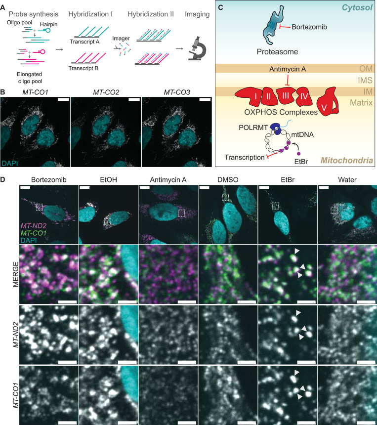
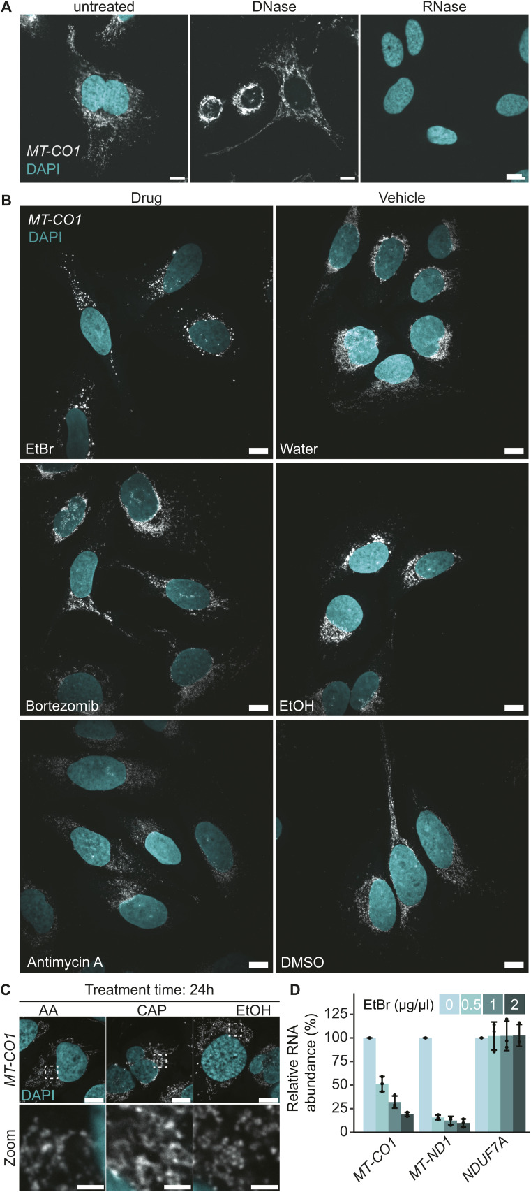
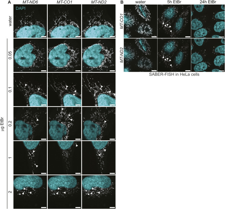
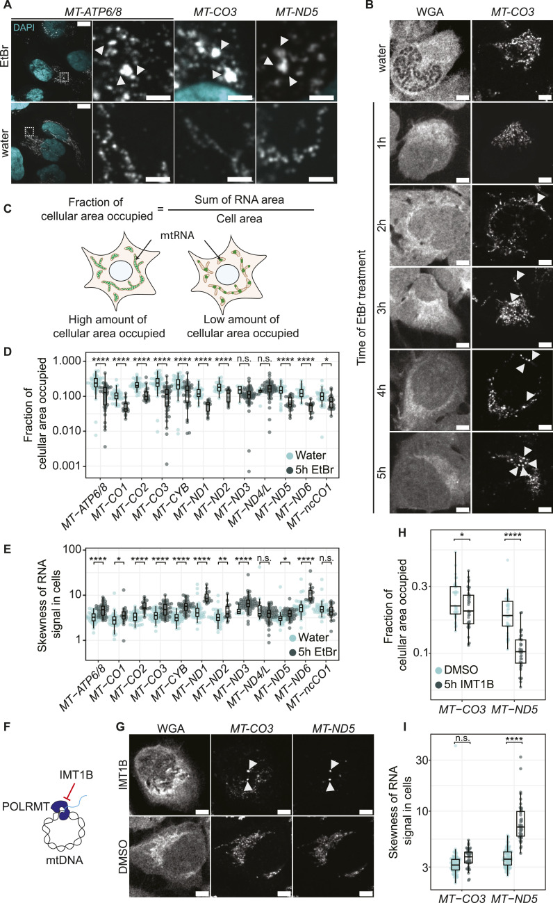
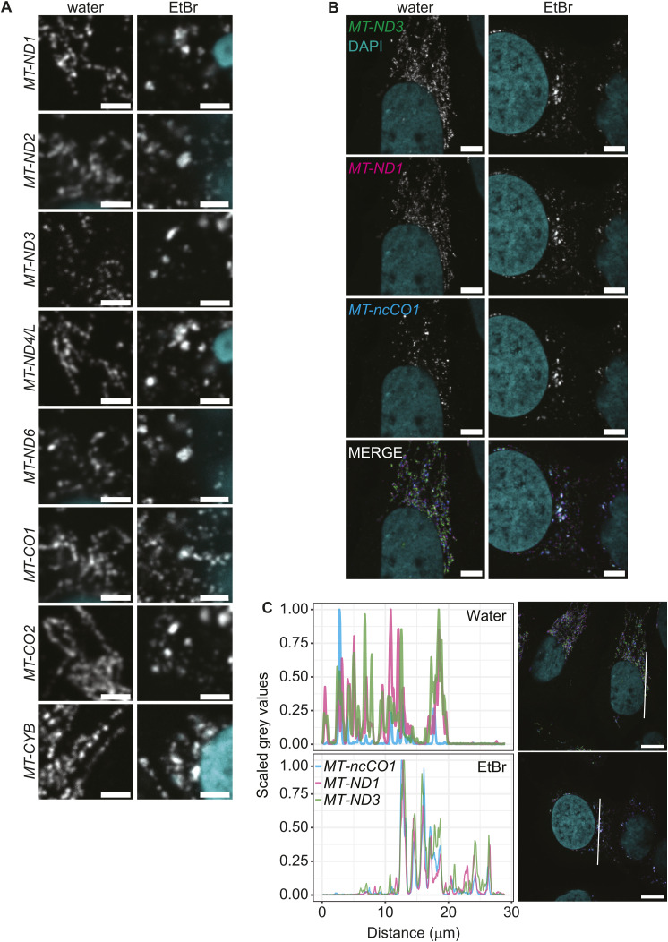
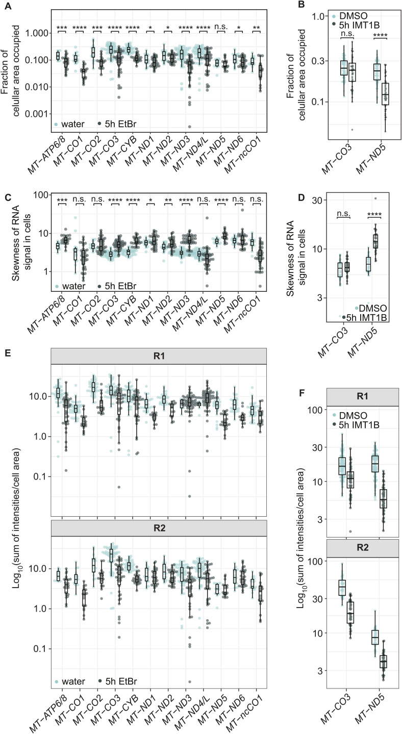
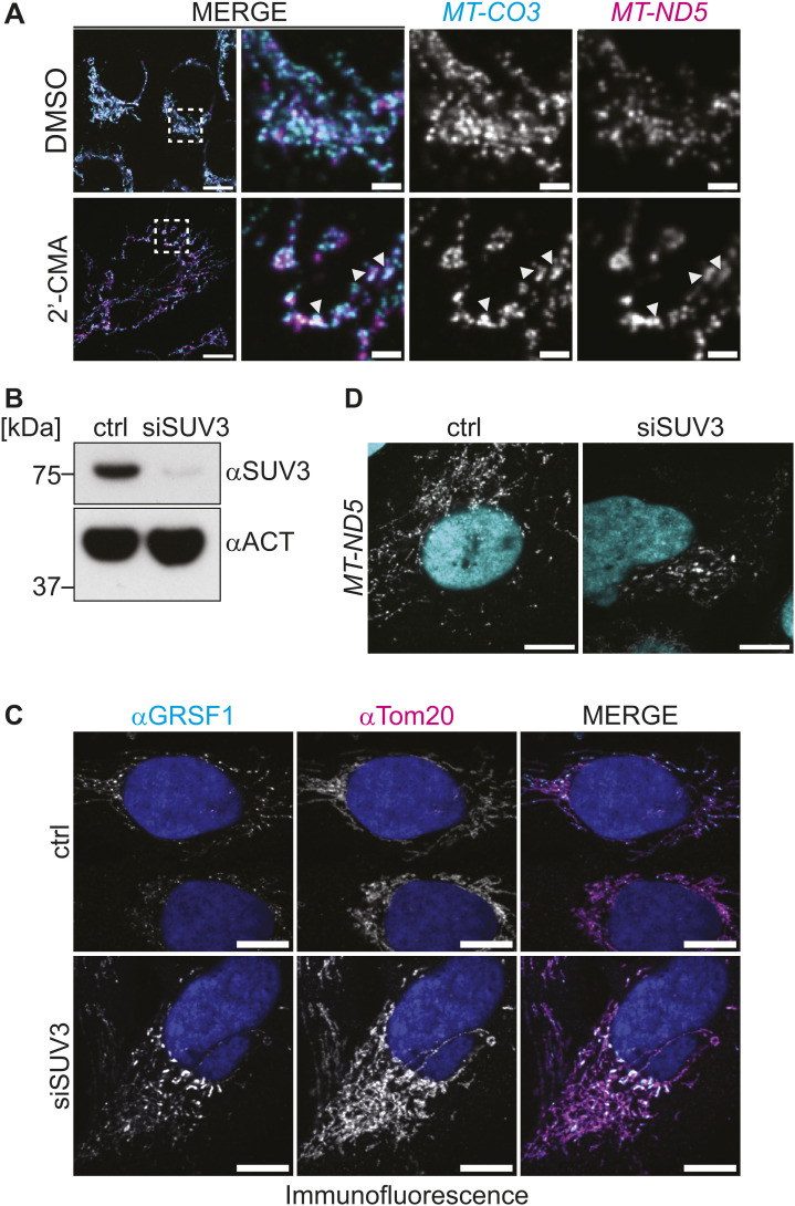
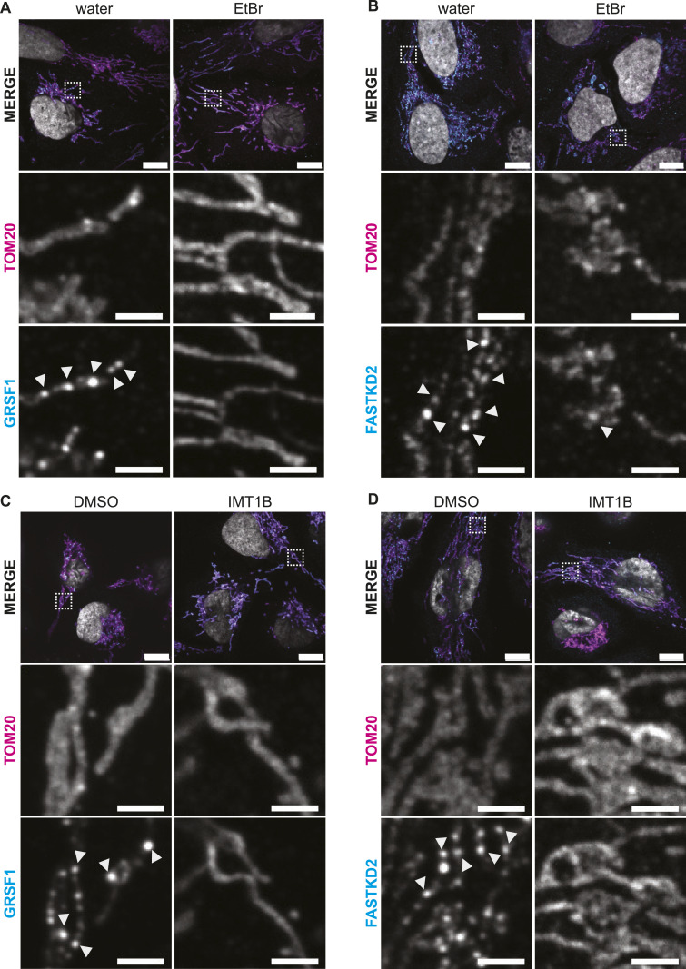
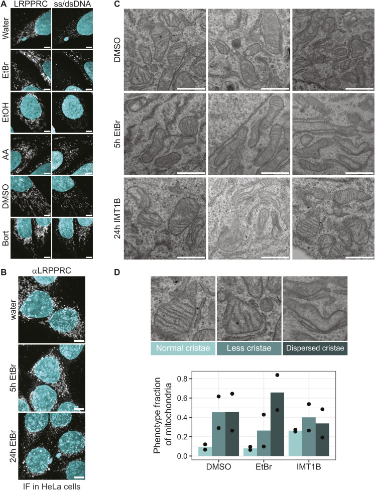
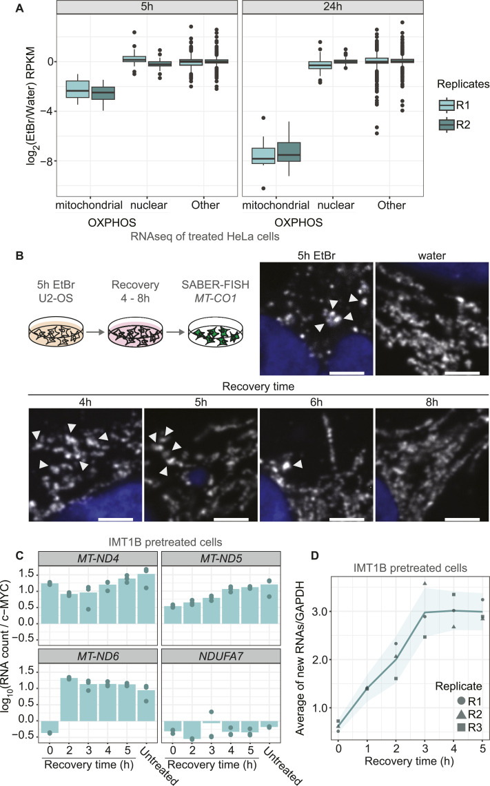
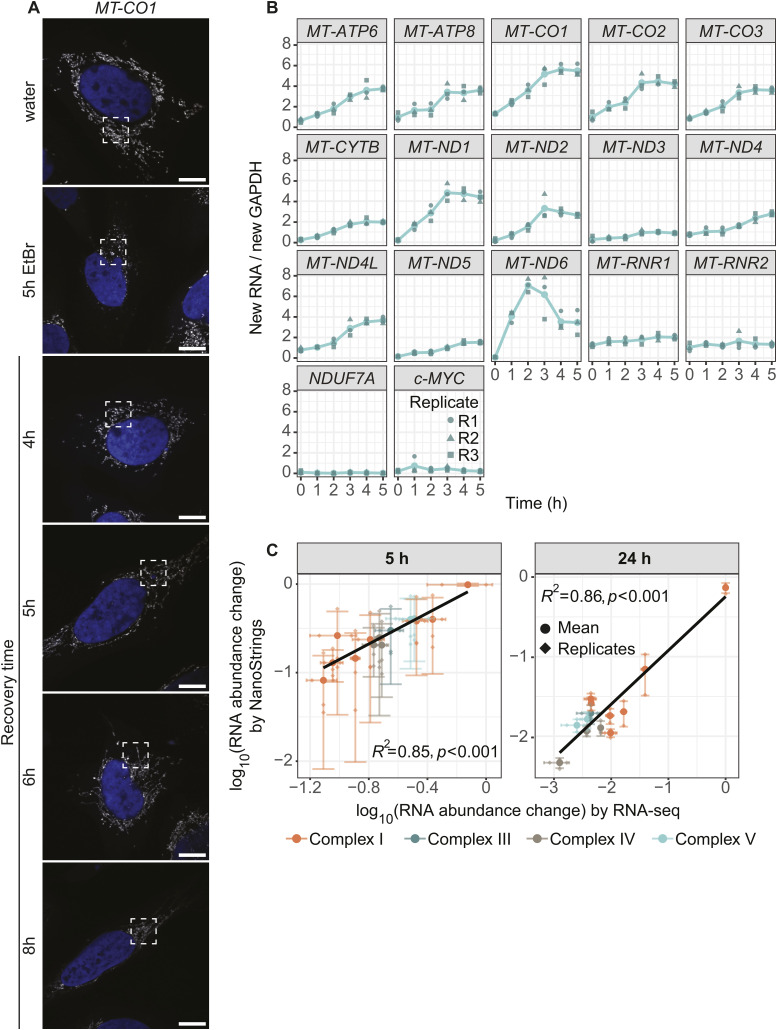
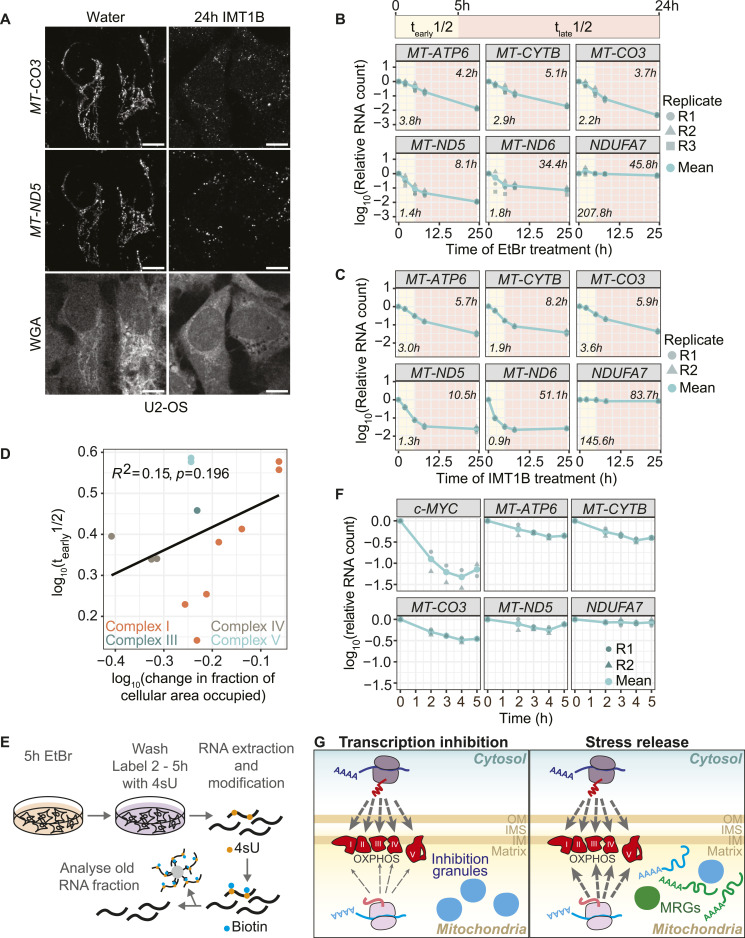
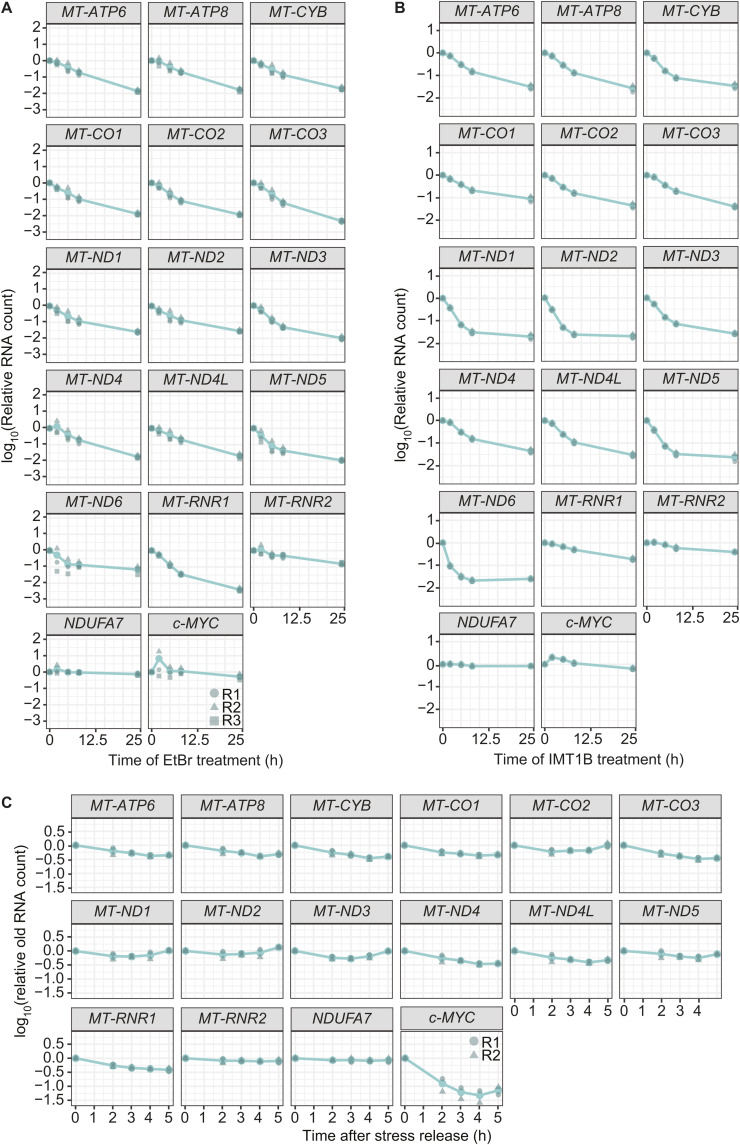
Mitochondrial gene expression regulation is required for the biogenesis of oxidative phosphorylation (OXPHOS) complexes, yet the spatial organization of mitochondrial RNAs (mt-RNAs) remains unknown. Here, we investigated the spatial distribution of mt-RNAs during various cellular stresses using single-molecule RNA-FISH. We discovered that transcription inhibition leads to the formation of distinct RNA granules within mitochondria, which we term inhibition granules. These structures differ from canonical mitochondrial RNA granules and form in response to multiple transcription arrest conditions, including ethidium bromide treatment, specific inhibition or stalling of the mitochondrial RNA polymerase, and depletion of the SUV3 helicase. Inhibition granules appear to stabilize certain mt-mRNAs during prolonged transcription inhibition. This phenomenon coincides with an imbalance in OXPHOS complex expression, where mitochondrial-encoded transcripts decrease while nuclear-encoded subunits remain stable. We found that cells recover from transcription inhibition via resolving the granules, restarting transcription, and repopulating the mitochondrial network with mt-mRNAs within hours. We suggest that inhibition granules may act as a reservoir to help overcome OXPHOS imbalance during recovery from transcription arrest.


Conflict of interest statement

The authors declare that they have no conflict of interest.

Figures

Figure 1.
Figure 1.. Ethidium bromide treatment leads to changes in the spatial distribution of the mitochondrial transcripts MT-CO1 and MT-ND2.
(A) Workflow of SABER-FISH. Oligo pools are elongated with the help of hairpins creating long overhangs. Pink and turquoise colors represent different sequences. In the first hybridization, probes bind to transcripts of interests. In the second hybridization, imager probes with fluorophores bind to the complementary overhangs followed by imaging. (B) Confocal fluorescence microscopy of multiplexed SABER-FISH of three different transcripts in U2-OS cells. The complex IV subunit transcripts MT-CO1, MT-CO2, and MT-CO3 were labeled. The scale bars represent 10 μm. (C) Scheme showing acting sites of the used drugs. Bortezomib inhibits the proteasome, antimycin A blocks oxidative phosphorylation complex III, and ethidium bromide (EtBr) intercalates into the mitochondrial DNA and subsequently inhibits transcription. (D) SABER-FISH for MT-CO1 (green in the MERGE panel) and MT-ND2 (magenta in the MERGE panel) after different drug treatments. Cells were treated with either 100 μM bortezomib, antimycin A, or 2 μg/ml EtBr for 5 h. The respective vehicle control was used and is shown next to the corresponding drug. Images of representative cells are shown. White boxes indicate areas that are shown enlarged underneath. Scale bars of full cell images represent 10 μm and of zoom-in represent 2 μm. White arrows mark clustered RNA in EtBr-treated cells. For all images shown in this study, if not otherwise mentioned, single z-planes were chosen. DAPI staining is shown in cyan and RNA staining in gray. All images in this figure were adjusted to represent the spatial distribution and not differences in intensities.
Figure S1.
Figure S1.. Mitochondrial RNAs form granules upon EtBr treatment.
(A) RNase and DNase treatment to test for oligo specificity of MT-CO1. Cells were treated after fixation and before the hybridization. Scale bars represent 10 μm. (B) SABER-FISH for MT-CO1 after 5 h of drug treatment. (D) Scale bar shows 10 μm. These fields of view were used for panel (D) in Fig 1. (C) SABER-FISH for MT-CO1 after 24 h of drug treatment with 100 nM antimycin A (AA), 200 μg/ml chloramphenicol (CAP), or EtOH as a control. DAPI stain is shown in cyan, and RNAs are shown in gray. White boxes mark areas chosen for zoom-ins. Scale bars of whole-cell panels represent 10 μm and of zoom-ins represent 2 μm. (D) Bar graph presenting the qRT-PCR to evaluate transcription arrest after 5 h of EtBr treatment. The y-axis shows the relative abundance of RNAs normalized to GAPDH. Three biological replicates were used and are plotted as single points. The error bar shows the SD. Source data are available for this figure.
Figure S2.
Figure S2.. First granules appear with 100 nM EtBr treatments.
(A) Titration of EtBr treatments for 5 h. First granules can be detected visually with 100 ng/ml EtBr. Shown are representative images of multiplexed MT-ND6, MT-ND2, and MT-CO1. RNAs are presented in gray, and DAPI staining of nuclei is shown in cyan. Arrowheads mark RNA granules. Scale bars are 5 μm. (B) SABER-FISH of EtBr-treated HeLa cells. RNAs are presented in gray, and DAPI staining of nuclei is shown in cyan. Arrowheads mark RNA granules. Scale bars are 5 μm.
Figure 2.
Figure 2.. Transcription arrest leads to the formation of RNA granules.
(A) Example transcripts forming RNA granules after EtBr treatment. U2-OS cells were treated for 5 h with either EtBr or water. Shown are whole cells for MT-ATP6/8–labeled cells and zoom-ins of cells labeled for MT-ATP6/8, MT-CO3, and MT-ND5. Arrowheads mark RNA granules. White boxes represent areas that are zoomed in. Scale bars represent 10 μm for whole cells and 2 μm for zoom-ins. Cyan represents DAPI staining of nuclei, and gray represents RNA staining. (B) Dynamics of RNA granule formation of MT-CO3 during EtBr treatment. Cells were treated for 5 h with water or increasing times with EtBr. Cells were stained with WGA, and RNAs were labeled by SABER-FISH. Scale bars represent 5 μm. Arrowheads mark RNA granules. (C) Schematic of the fraction of cellular area occupied measurement. The fraction of cellular area occupied is calculated by the RNA area divided by the cell area. A high fraction of the cellular area occupied represents a high distribution of mitochondrial RNA in the network, that is, in the cell. A low fraction of cellular area occupied represents a more granular state. (D) Quantification of the fraction of cellular area occupied for cells of three fields of view for each transcript. Single points represent a single cell. Boxplots show the median, and the first and third quartiles, and the whiskers show a maximum of 1.5 times of the interquartile range. Green represents EtBr-treated cells, turquoise represents cells treated with water, and the treatment time was 5 h. The y-axis shows the measured fraction of cellular area occupied in a log10 scale. (E) Quantification of the skewness of RNA signals in cells. The y-axis shows the skewness measured in the log10 scale. (F) IMT1B inhibits POLRMT directly. (G) Representative images of cells treated for 5 h with either 10 μM IMT1B or DMSO. Cells were stained with WGA, and RNA-FISH was performed for MT-CO3 and MT-ND5. Scale bars represent 5 μm. Arrowheads mark RNA granules. (H) Quantification of the fraction of cellular area occupied after IMT1B treatment shown as boxplots. Single points represent a single cell. Green represents IMT1B-treated cells, turquoise represents cells treated with DMSO, and treatment time was 5 h. The y-axis shows the measured cellular area occupied in the log10 scale. (I) Quantification of the skewness of RNA signals in cells after IMT1B treatment. The y-axis shows the skewness measurement in the log10 scale. (D, E, H, I) n.s., nonsignificant, *P > 0.05, **P > 0.01, ****P > 0.0001; one-sided t test was used. For detailed P-values, see also Table S4. All images in this figure were adjusted to represent the spatial distribution and not differences in intensities.
Figure S3.
Figure S3.. Granule formation is a global response to EtBr treatment.
(A) Example images for residual mt-mRNAs not shown in Fig 2A. All mt-mRNAs form granules upon EtBr treatment. Scale bars represent 2 μm. (B) SABER-FISH for MT-ncCO1 (blue) multiplexed with MT-ND1 (magenta) and MT-ND3 (green). With merge labeled is the overlay of all channels. The scale bars represent 5 μm. (C) Line profiles showing the signal distribution of the different labeled transcript along a distance of 30 μm. The gray values were scaled according to their minimum and maximum to make them comparable. Micrographs right to the plots show the area measured marked with a white line.
Figure S4.
Figure S4.. RNA abundance decreases upon transcription arrest.
(A, B) Single-cell data of biological replicates of a quantified fraction of cellular area occupied after either EtBr or IMT1B treatment. Single points represent a single cell. Green represents drug-treated cells, turquoise represents cells treated with water or DMSO, and treatment time was 5 h. The y-axis shows the measured cellular area occupied in the log10 scale. For detailed P-values, see Table S4. (C, D) Single-cell data of biological replicates of the skewness of RNA signals in the cell after EtBr or IMT1B treatment. Single points represent measurements of a single cell. The drug is shown in dark green and the vehicle control in turquoise. The skewness is shown on the y-axis in the log10 scale. (E) Boxplots showing the distribution of intensities measured in cells. Single points represent a cell. To measure intensities, the integrated intensities measured of RNA objects were summed per cell and normalized to the cell area. The y-axis presents the normalized summed intensities on a log10 scale. Drug is shown in dark green and the vehicle control in turquoise. (E, F) Intensity measurements of single cells upon IMT1B treatment. Intensities are represented as described in panel (E). Boxplots show the median, and the first and third quartiles, and the whiskers show a maximum of 1.5 times of the interquartile range. n.s. = nonsignificant, *P > 0.05, **P > 0.01, ***P > 0.001, ****P > 0.0001, calculated with a one-sided t test.
Figure S5.
Figure S5.. Transcription inhibition induces granule formation.
(A) Adenosine analog 2′-CMA induces granules similar to EtBr and IMT1B treatment. Multiplexing of MT-CO3 (cyan) and MT-ND5 (magenta) is shown. The scale bar represents 10 μm for the whole-cell panel and 2 μm for the zoom-in panels. Arrows mark granules. (B) Control Western blot of U2-OS cells treated with a nontargeting siRNA (ctrl) and siRNAs targeting SUV3 for 72 h. SUV3 depletion was highly effective. (C) Immunofluorescence after 72 h of siRNA treatment to deplete SUV3 in U2-OS cells. GRSF1 is shown in cyan and TOM20 in magenta. DAPI stain is shown in blue. The scale bars represent 10 μm. (D) SABER-FISH after siRNA treatment to deplete SUV3. Cells were treated for 72 h. RNAs are presented in gray, and DAPI staining of nuclei is shown in cyan. Scale bars are 10 μm. All images in this figure were adjusted to represent the spatial distribution and not differences in intensities. Source data are available for this figure.
Figure 3.
Figure 3.. Mitochondrial RNA granule markers GRSF1 and FASTKD2 are not part of inhibition granules.
(A, C) Immunofluorescence of cells treated for 5 h with EtBr, water, IMT1B, or DMSO. TOM20 was used as a mitochondrial marker in all panels. TOM20 is shown in magenta in the MERGE panel and GRSF1 in cyan. (B, D) Immunofluorescence of cells treated for 5 h with EtBr, water, IMT1B, or DMSO. TOM20 was used as a mitochondrial marker in all panels. TOM20 is shown in magenta in the MERGE panel and FASTKD2 in cyan. DAPI is shown in gray. Boxes in MERGE panels represent areas enlarged. Zoom-ins show RNA staining in gray. Arrowheads mark mitochondrial RNA granules. Scale bars in whole-cell panels represent 10 μm and in zoom-ins represent 2 μm.
Figure S6.
Figure S6.. Integrity of the mitochondrial network is not strongly affected.
(A) Immunofluorescence for LRPPRC and mitochondrial DNA (ss/dsDNA) after different drug treatments is shown. Cells were treated with Bort (bortezomib), AA (antimycin A), or EtBr (ethidium bromide) and the respective vehicle controls. LRPPRC and IF-labeled DNA are shown in gray. DAPI stain is shown in cyan. Some cells show swollen mitochondria after EtBr treatment, whereas others have normal mitochondria. Scale bars show 5 μm. All images in this figure were adjusted to represent the spatial distribution and not differences in intensities. (B) Immunofluorescence for LRPPRC in HeLa cells after EtBr treatment for 5 or 24 h. LRPPRC is presented in gray, whereas cyan shows the nuclei stained by DAPI. The mitochondrial network is affected after 24 h of EtBr treatment. Scale bars show 5 μm. All images in this figure were adjusted to represent the spatial distribution and not differences in intensities. (C) Transmission electron microscopy of cells treated for 24 h with IMT1B, DMSO or for 5 h with EtBr. Bars show 1 μm. Shown are three zoom-ins of three different cells. Mitochondrial morphology is not majorly disturbed. (D) Bar graph representing the quantification of the transmission electron microscopy images. The panels show how mitochondria were categorized. The fraction of each category for the different conditions is shown. Presented is the mean of two independent countings, and the black dots represent the single countings. Source data are available for this figure.
Figure 4.
Figure 4.. Cells recover from transcription arrest.
(A) RNA-seq after EtBr or water treatment for 5 or 24 h of HeLa S3 cells. Boxplots represent the distribution change for mitochondrial-encoded, nuclear-encoded oxidative phosphorylation subunits and other (residual transcriptome) transcripts for two biological replicates. The y-axis shows the log2 change of EtBr over the water control in RPKM. (B) Confocal microscopy of MT-CO1 distribution changes in the mitochondrial network during recovery. U2-OS cells were pretreated for 5 h with EtBr, washed, and grown in normal media for 4 up to 8 h. SABER-FISH for MT-CO1 was performed, and the cells were imaged. Shown is SABER-FISH after 5 h of EtBr and water treatment as controls. Zoom-ins are shown for the different recovery time points and for the control panels. Whole cells can be found in Fig S7A. Scale bars represent 2 μm. White arrowheads mark RNA granules. All images in this figure were adjusted to represent the spatial distribution and not differences in intensities. (C) Relative RNA counts of cells during recovery of IMT1B-treated cells. Cells were pretreated with 10 μM IMT1B, washed, and grown in normal media. In the last 10 min of each time point, 4sU was added. RNA levels were measured after 0, 2, 3, 4, and 5 h of recovery by MitoStrings and their counts normalized to RNA counts of c-MYC. The y-axis shows the log10 scale of relative RNA counts of either MT-ND4, MT-ND5, MT-ND6, or NDUF7A as a cytosolic control. Shown is the mean of three biological replicates, and points represent the individual replicates. (D) Metagene plot of transient transcription analysis during recovery. 4sU-labeled RNAs were biotinylated and enriched on streptavidin beads. Eluted RNAs were then measured by MitoStrings. Shown are the averaged relative counts of all 4sU-labeled mt-mRNAs normalized to 4sU-labeled GAPDH on the y-axis. The x-axis shows the time course of 0, 1, 2, 3, 4, and 5 h. Shown is the mean of the average of three biological replicates in dark green. In dark gray green and in different shapes are the single replicates plotted to show the variation of the experiment. The turquoise ribbon represents the 95% confidence interval.
Figure S7.
Figure S7.. Cells recover after release of transcription arrest.
(A) Whole-cell images corresponding to zoom-ins shown in Fig 4B. MT-CO1 is shown in gray and DAPI in blue. White boxes mark areas used for zoom-ins. Scale bars represent 10 μm. Images are adjusted to show the spatial distribution of RNAs and not to compare intensities. (B) Transient transcription during recovery after IMT1B treatment. Shown are relative RNA counts of 4sU-labeled RNAs normalized to 4sU-labeled GAPDH on the y-axis. The x-axis shows the time points of recovery in hours. In turquoise, the mean of three biological replicates is shown as a line plot. The biological replicates are shown in dark green and in different shapes. (C) Correlation plot to compare the NanoStrings data with RNA-seq data after 5 or 24 h of EtBr treatment. NanoStrings data shown on the y-axis were first normalized to GAPDH and afterward compared with the 0-h control. The x-axis shows the RNA-seq data. For the 24-h sample, MT-ND3 was not used in the correlation as it was not detected in the EtBr 24-h RNA-seq sample. The single oxidative phosphorylation subunits measured are colored according to their complex, subunits of Complex I in orange, Complex III in dark green, Complex IV in brown, and Complex V in turquoise. Big dots represent the mean of biological replicates. The single replicates are plotted along the corresponding axis including the SD as an error bar. Shown is the r2 of Pearson’s correlation.
Figure 5.
Figure 5.. Inhibition granules show protectivity for parts of mt-mRNAs.
(A) SABER-FISH for MT-CO3 and MT-ND5 after 24 h of IMT1B or DMSO treatment in U2-OS cells. RNAs are shown in gray, as well as WGA staining of cells. Scale bars represent 10 μm. Signals were adjusted to represent the spatial distribution and not for intensity comparisons. (B) Degradation kinetics of representative mt-mRNAs in EtBr long-term treatment. Cells were incubated for 0 up to 24 h in EtBr media. RNAs were extracted, and RNA abundance was measured by MitoStrings. The y-axis shows the log10 of the RNA counts normalized to the counts of GAPDH. The x-axis shows the treatment time in hours. The bar underneath represents the time frames used to calculate half-lives for early (tearly1/2) and late time points (tlate1/2). Shown is the mean of three biological replicates in turquoise. In dark green and different shapes, the single biological replicates are shown. The numbers in the left lower corner represent early half-lives and in the upper right corner the late half-lives. (C) Degradation kinetics of representative mt-mRNAs in IMT1B long-term treatment. Cells were incubated for 0 up to 24 h in IMT1B media. RNAs were extracted, and RNA abundance was measured by MitoStrings. The y-axis shows the log10 of the RNA counts normalized to the counts of GAPDH. The x-axis shows the treatment time in hours. The bar underneath represents the time frames used to calculate half-lives for early (tearly1/2) and late time points (tlate1/2). Shown is the mean of two biological replicates in turquoise. In dark green and different shapes, the single biological replicates are shown. The numbers in the left lower corner represent early half-lives and in the upper right corner the late half-lives. (D) Comparison of the early half-lives calculated for the EtBr-treated cells with the change of the fraction of the cellular area occupied. The y-axis shows the half-lives in the log10 space. The x-axis shows the mean of the change in the fraction of the cellular area occupied of the two replicates in the log10 space. The change was calculated by dividing the median of the fraction of the cellular area occupied after 5 h of EtBr treatment by the median of the water control. The single data are shown in Fig 2D. The subunits were colored according to their complex, subunits of Complex I in orange, of Complex III in dark green, of Complex IV in brown, and of Complex V in turquoise. Pearson’s correlation coefficient R2 was used. (E) MitoStrings analysis of representative unlabeled granular RNAs after stress release. Cells were treated for 5 h with EtBr, washed, and grown in media supplemented with 4sU for 0, 2, 3, 4, and 5 h. RNAs were extracted, and 4sU (shown in orange)-labeled RNA was biotinylated (biotin is shown in blue). Biotinylated RNA was bound onto streptavidin beads, and the flow-through, representing the unlabeled RNA fraction, was used for MitoStrings. (F) Graph showing decrease in unlabeled RNAs after stress release. The y-axis shows the log10 of RNA levels normalized to an unlabeled spike-in, added during RNA extraction. (G) During transcription inhibition, mitochondrial RNAs form inhibition granules and the oxidative phosphorylation (OXPHOS) expression inside mitochondria is decreased, whereas the nuclear expression of OXPHOS subunits remains unchanged. During stress release, OXPHOS expression will eventually increase again. Inhibition granules might help in recovery through release of stored RNAs. Mitochondrial RNA granules will form again and replenish the mitochondrial network with RNAs. Inhibition granules are shown in blue and mitochondrial RNA granules in green.
Figure S8.
Figure S8.. Degradation kinetics after long-term stress treatments.
(A) Shown are the different degradation kinetics of the different mitochondrial RNAs during long-term EtBr treatment. Presented is the mean of three biological replicates. Single replicates are shown in dark green and as different shapes. The y-axis shows log10 of RNA counts normalized to GAPDH counts. Single transcripts are shown as representatives in Fig 5B. (B) Graphs represent the different degradation kinetics of the different mitochondrial RNAs during long-term IMT1B treatment. Shown is the mean of two biological replicates, as well as the single replicates in dark green and as different shapes. Representative transcripts of this set are shown in Fig 5C. (C) Shown is the change of old RNA levels upon stress release. The mean of two biological replicates is shown in turquoise and individual replicates in dark green. The RNA counts were normalized to an unlabeled spike-in. The y-axis shows the log10 of spike-in normalized RNA counts. Representative transcripts of this set are shown in Fig 5F.

Similar articles

References

    1. Anderson P, Kedersha N (2009) RNA granules: Post-transcriptional and epigenetic modulators of gene expression. Nat Rev Mol Cell Biol 10: 430–436. 10.1038/nrm2694 - DOI - PubMed
    1. André AM, Spruijt E (2020) Liquid-liquid phase separation in crowded environments. Int J Mol Sci 21: 5908. 10.3390/ijms21165908 - DOI - PMC - PubMed
    1. Antonicka H, Shoubridge EA (2015) Mitochondrial RNA granules are centers for posttranscriptional RNA processing and ribosome biogenesis. Cell Rep 10: 920–932. 10.1016/j.celrep.2015.01.030 - DOI - PubMed
    1. Antonicka H, Sasarman F, Nishimura T, Paupe V, Shoubridge EA (2013) The mitochondrial RNA-binding protein GRSF1 localizes to RNA granules and is required for posttranscriptional mitochondrial gene expression. Cell Metab 17: 386–398. 10.1016/j.cmet.2013.02.006 - DOI - PubMed
    1. Begeman A, Smolka JA, Shami A, Waingankar TP, Lewis SC (2025) Spatial analysis of mitochondrial gene expression reveals dynamic translation hubs and remodeling in stress. Sci Adv 11: eads6830. 10.1126/sciadv.ads6830 - DOI - PMC - PubMed

LinkOut - more resources