. 2025 Jul 1;19(25):23465-23478.
doi: 10.1021/acsnano.5c07356. Epub 2025 Jun 22.

Bionic Perception of Surface Adhesion via a Magnetized Spring-like Sensor with Axial Stretchability

Affiliations

Bionic Perception of Surface Adhesion via a Magnetized Spring-like Sensor with Axial Stretchability

Yuanzhe Liang et al. ACS Nano. .

Abstract

Perception of surface adhesion is one essential capability of a human fingertip, which is normally realized by touching the target surface with subsequent skin vibrations. However, such functionality is difficult to realize in flexible sensors and robotic systems due to the challenges in axial stretchability with reliable electrical feedback. In this study, we developed a bionic three-dimensional flexible magnetized spring (3D-FMS) that can quantitatively recognize surface adhesion based on electromagnetic induction. Combined with the laser processing with predefined patterns, we show that a raw flexible cube can be converted to highly stretchable spring-like geometry with excellent bidirectional deformation in axial orientation. Furthermore, the mechanical elongation caused by adhesion is critical for the induced voltage signals, allowing us to establish a model that relates adhesion strength with electrical outputs in a linear behavior. Via optimization of the process parameters, the device exhibits tailored stiffness to modulate the sensing sensitivity and working range on demand. With the established interactive interface, the wearable tests and robotic integration demonstrate the potential of the 3D-FMS for adhesion perception as a human fingertip. We expect that the strategy will offer a valuable reference to explore 3D wearable devices that advances robotic systems with more bionic functions such as stickiness determination.

Keywords: 3D magnetized spring; adhesion recognition; flexible tactile sensor; laser processing; stickiness.


Figures

1
1
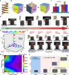
(a) Schematic diagram of how humans feel surface adhesion via touching a surface with signals transmitted through neural receptors. (b) Schematic diagram of the process when fingertip skins touch, press, and detach from an adhesive surface with vibration. (c) The traditional Chinese food cutting technique “Basket Weaving Cut Technique” for a stretchable cucumber. (d) Optical images of the miniature 3D-FMS with demonstration of flexibility and stretchability. (e) Diagrams of the spring model and the magnetic flux distribution of the magnetized 3D-FMS. (f) Schematic diagram of the sensing principle for surface adhesion based on the developed device.
2
2
(a) Schematic diagram of the spring model with key parameters that affect the stretching/compressing performance. (b) Schematic diagram of the key parameters that play an important role in the 3D-FMS performance, including bottom side length (L), height (H), and cutting angle (θ), space (S), and cycle (C). (c) Schematic diagram of the experimental setup to measure the stiffness of 3D-FMS. (d) Stretching behavior of the 3D-FMS prepared by different cutting cycles. All samples were prepared via a space of 0.5 mm and angle of 15°. (e) Stiffness values based on different combinations of the cutting angle, space, and cycle during laser processing. (f) Optical images of the stretching behavior from different devices when the cutting space and angle were varied. The spring models were also provided, and all samples were prepared via a cycle of 80. (g) Stiffness of the laser-processed 3D-FMS based on different NdFeB and Ecoflex contents in the composite matrix. (h) Formation summary of the 3D-FMS based on different dimension of the raw body and cutting cycles. In the y-axis, C means cycle; in the x-axis, L and H indicate the length and height of the device.
3
3
(a) Schematic diagram of the experimental setup for magnetic field intensity measurement. The green arrow shows the stretching direction. (b) Magnetic field intensity variations in the Z-axis when the 3D-FMS is stretched and released at specific length. (c) Dependence of peak voltage values on the prestretch length of the device. (d) Real-time record of the mechanical deformation when the 3D-FMS was exposed to adhesive tape. The scale bar is 3 mm for all optical images. (e) Schematic diagram of the experimental setup for adhesion measurement of four 3D-FMS with different stiffness. (f) Relationship between peak voltage and adhesion strength from different devices. (g) Summary of the effect of device stiffness on the sensitivity and the sensing range.
4
4
(a) Induced voltage values when different motion speeds were applied on the 3D-FMS to move toward the adhesive tape for measurement. (b) Comparison of the actual and sensed adhesion values across different motion speeds. (c) Evaluation of long-term stability of the 3D-FMS via periodical deformation up to 1000 cycles. (d) Distribution density of the induced voltage across different sensing cycles. (e) Peak voltages obtained from different samples prepared by the same templates and fabrication parameters during the laser processing. All tests were processed with the same type of adhesive tape and the maximum pressure. (f) Schematic diagram of the regional tape with different adhesion after cyclic uses. (g) Comparison of the actual and sensed voltage signals when the device was applied to the tape that has been used for different cycles.
5
5
(a) Experimental setup for wearable demonstration, which is composed of a LabVIEW interface and the force gauge with a sensing platform. When touching the nonadhesive or adhesive regions, the 3D-FMS exhibits different behaviors to induce signal profiles for display. (b) Schematic diagram of the mechanical behaviors when 3D-FMS was pressed toward the nonadhesive and adhesive regions. (c) Relationship between the sensed adhesion and the applied force when the device was pressed against nonadhesive or adhesive area. (d) Results of sensed adhesion values from four volunteers when pressing the nonadhesive or adhesive regions. (e) Schematic diagram of surface adhesion perception for robots in daily operation. (f) Optical images of the experimental setup by attaching 3D-FMS onto a robotic arm to simulate the sensing process. When touching the adhesive region, a “warning” red light will be triggered, and the touch of the nonadhesive region would trigger the green “safe” light.

Similar articles

References

    1. Zhang Z. R., Wang X., Liu J., Dai C. S., Sun Y.. Robotic Micromanipulation: Fundamentals and Applications. Annu. Rev. Control Robot. 2019;2:181–203. doi: 10.1146/annurev-control-053018-023755. - DOI
    1. Flores-Abad A., Ma O., Pham K., Ulrich S.. A Review of Space Robotics Technologies for On-Orbit Servicing. Prog. Aerosp. Sci. 2014;68:1–26. doi: 10.1016/j.paerosci.2014.03.002. - DOI
    1. Galloway K. C., Becker K. P., Phillips B., Kirby J., Licht S., Tchernov D., Wood R. J., Gruber D. F.. Soft Robotic Grippers for Biological Sampling on Deep Reefs. Soft Robot. 2016;3(1):23–33. doi: 10.1089/soro.2015.0019. - DOI - PMC - PubMed
    1. Lane D. M., Davies J. B. C., Casalino G., Bartolini G., Cannata G., Veruggio G., Canals M., Smith C., O’Brien D., Pickett M.. et al. AMADEUS: Advanced Manipulation for Deep Underwater Sampling. IEEE Robot. Autom. Mag. 1997;4(4):34–45. doi: 10.1109/100.637804. - DOI
    1. Chita-Tegmark M., Scheutz M.. Assistive Robots for the Social Management of Health: A Framework for Robot Design and Human-Robot Interaction Research. Int. J. Soc. Robot. 2021;13(2):197–217. doi: 10.1007/s12369-020-00634-z. - DOI - PMC - PubMed

LinkOut - more resources