. 2025 Jan 31;14(5):103433.
doi: 10.1016/j.eats.2025.103433. eCollection 2025 May.

Labral Scaffolding Technique Utilizing Dermal Allograft to Address Subcritical Glenoid Bone Loss in Glenoid Labrum Repair

Affiliations

Labral Scaffolding Technique Utilizing Dermal Allograft to Address Subcritical Glenoid Bone Loss in Glenoid Labrum Repair

Sohail Qazi et al. Arthrosc Tech. .

Abstract

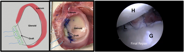
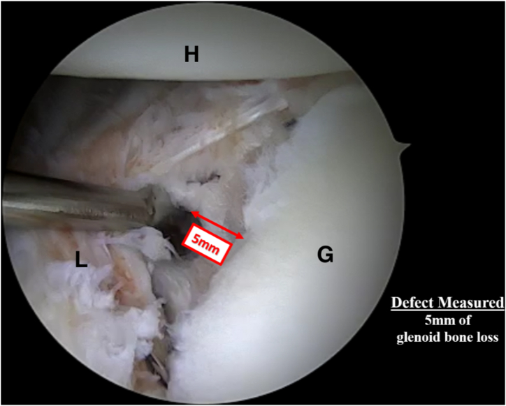
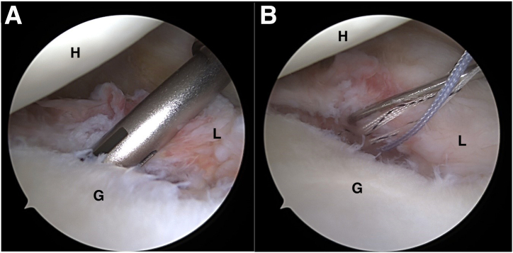
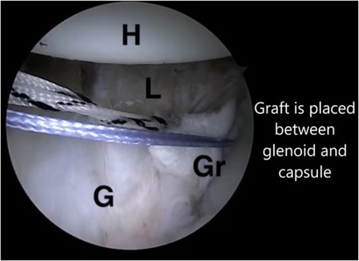
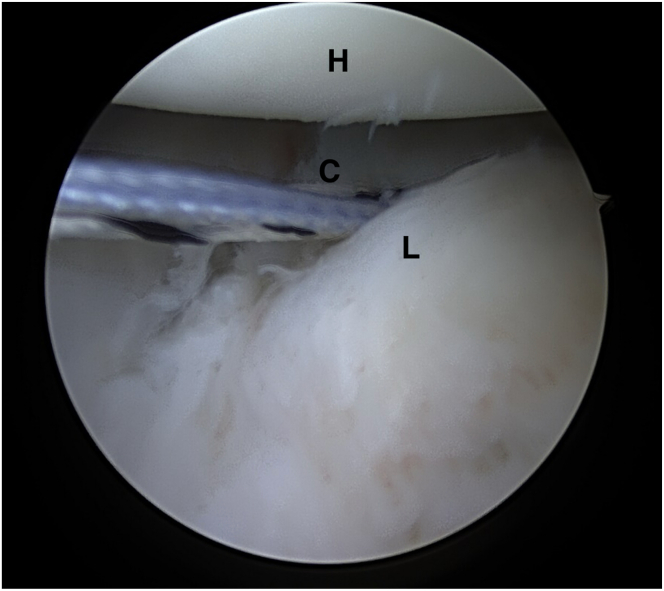
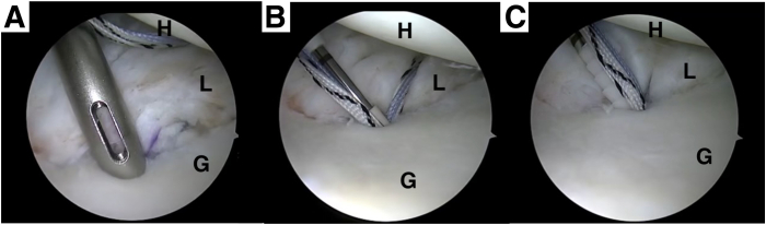
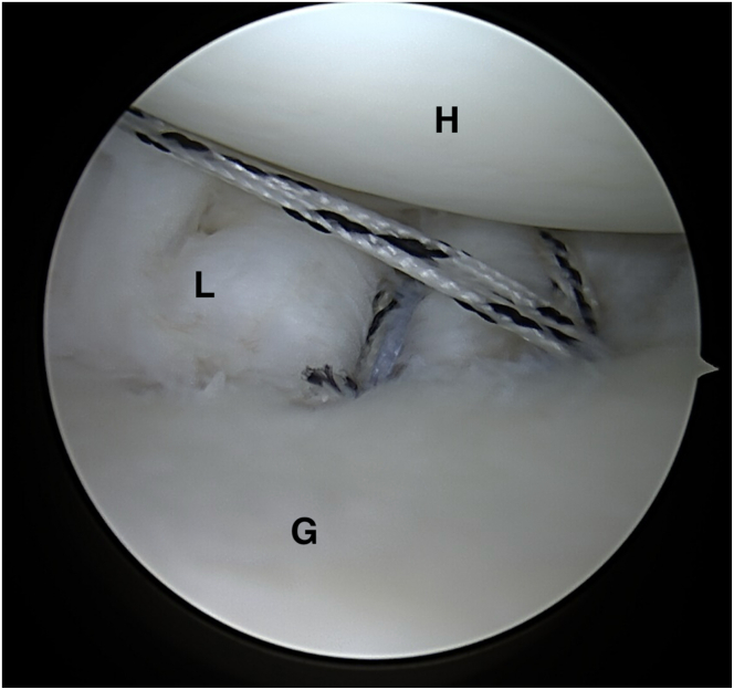
A treatment gap exists in the treatment of shoulder instability with subcritical bone loss. In this population, standard arthroscopic labral repairs have been associated with high failure rates. Bone block procedures are associated with low rates of recurrent instability but are associated with a high complication rate and subsequent long-term degenerative changes, making its use less than optimal in subcritical bone loss. We describe the arthroscopic "labral scaffold" technique using dermal allograft with labral reconstruction to address subcritical glenoid bone loss. This technique utilizes a dermal allograft to augment the bony deficit to better restore more native glenohumeral biomechanics with a double-row labral repair and subsequent labral reconstruction.


Conflict of interest statement

All authors (S.Q., J.A., D.W., S.A.) declare that they have no known competing financial interests or personal relationships that could have appeared to influence the work reported in this paper.

Figures

Fig 1
Fig 1
Schematic (left) and cadaveric (middle) representation of the labral scaffold technique for subcritical glenoid bone loss. The humeral head (H), repaired labrum (L), and glenoid (G) are shown arthroscopically on the right. The patient was positioned in the left lateral decubitus position with a standard posterior viewing portal and a standard anterior portal for instrumentation.
Fig 2
Fig 2
Diagnostic arthroscopy from the lateral decubitus position from the posterior portal with a 70° arthroscope, probing to measure glenoid bony defect size and extent of labral tear. Top is torn labrum (L) being held up by a probe; bottom is the glenoid (G). The patient was positioned in the left lateral decubitus position with a standard posterior viewing portal and a standard anterior portal for instrumentation.
Fig 3
Fig 3
Establishing a pocket for the dermal allograft between the glenoid and the capsule. Humeral head (H) is shown at the top, and labrum (L) and glenoid (G) are on the left and right, respectively. The patient was positioned in the left lateral decubitus position with a standard posterior viewing portal and a standard anterior portal for instrumentation.
Fig 4
Fig 4
Intraoperative measurement of anterior glenoid bone loss and sizing of the graft. Humeral head (H) is shown at the top, and labrum (L) and glenoid (G) are on the left and right, respectively. The patient was positioned in the left lateral decubitus position with a standard posterior viewing portal and a standard anterior portal for instrumentation.
Fig 5
Fig 5
Knotless single-loaded all-suture anchor (FiberTak; Arthrex) is placed just below the articular margin. Humeral head (H) is shown at the top, and the glenoid (G) is at the bottom. The labrum (L) before (A) and after (B) suture placement is shown in the center. The patient was positioned in the left lateral decubitus position with a standard posterior viewing portal and a standard anterior portal for instrumentation.
Fig 6
Fig 6
(A) ArthroFlex (Lifenet) graft is sharply cut with No. 15 blade to make 1-cm × 1-cm “blocks” to customize the patient-specific defect size. (B) Blocks are stacked to restore a 3-mm-thick defect. The patient was positioned in the left lateral decubitus position with a standard posterior viewing portal and a standard anterior portal for instrumentation.
Fig 7
Fig 7
A suture-passing device is used to pass a suture link through the graft. (A-C) Passage of the suture in temporal sequence. The patient was positioned in the left lateral decubitus position with a standard posterior viewing portal and a standard anterior portal for instrumentation.
Fig 8
Fig 8
Suture links passed in opposite directions through the stacked graft to create a mattress on the field. The patient was positioned in the left lateral decubitus position with a standard posterior viewing portal and a standard anterior portal for instrumentation.
Fig 9
Fig 9
The repair stitch is passed through the looped linked sutures in the graft to create a mattress. The patient was positioned in the left lateral decubitus position with a standard posterior viewing portal and a standard anterior portal for instrumentation.
Fig 10
Fig 10
A single suture tape link is placed through the loop of the mattress created by the repair stitch. This will be used as a countertraction suture to take slack from the knotless mechanism and, once cinched, will provide an additional suture to pass through the capsule. IT IS EXTREMELY IMPORTANT TO NOT CINCH THE LINK UNTIL THE GRAFT IS IN THE APPROPRIATE POSITION AGAINST THE GLENOID. If this suture is cinched early, the repair suture will not slide when pulled. The patient was positioned in the left lateral decubitus position with a standard posterior viewing portal and a standard anterior portal for instrumentation.
Fig 11
Fig 11
Grasping device used to introduce the graft past the dam of cannula. The patient was positioned in the left lateral decubitus position with a standard posterior viewing portal and a standard anterior portal for instrumentation.
Fig 12
Fig 12
Graft slid into place between the glenoid and capsule using the repair stitch (blue stitch) and link suture as a traction stich (striped black and white suture) to take the slack out of the repair. Once the graft is in the appropriate position, the linked suture (black and white suture) can be cinched to create an additional suture on the back of the graft that can be used for capsulorraphy. The patient was positioned in the left lateral decubitus position with a standard posterior viewing portal and a standard anterior portal for instrumentation. (G, glenoid; Gr, graft; H, humerus; L, labrum.)
Fig 13
Fig 13
The linked suture (black and white) is passed through the capsule and will be the main stitch used for the capsular tightening. The patient was positioned in the left lateral decubitus position with a standard posterior viewing portal and a standard anterior portal for instrumentation. (C, capsule; Gr, graft; H, humerus; L, labrum.)
Fig 14
Fig 14
The repair stitch from the anchor (blue) is passed through the labrum while also encorporating some of the capsule near the glenoid. Since this suture sits on top of the graft, as shown in Figure 12, it will force the graft down in an extra-articular position. The patient was positioned in the left lateral decubitus position with a standard posterior viewing portal and a standard anterior portal for instrumentation. (C, capsule; H, humerus; L, labrum.)
Fig 15
Fig 15
Suture link and repair stitch are brought over the top of the graft and loaded into an anchor, which is placed on the face of the glenoid. (A) Drilling for the anchor. (B) Islet with suture link and repair stitch loaded. (C) Anchor placement. The patient was positioned in the left lateral decubitus position with a standard posterior viewing portal and a standard anterior portal for instrumentation. (G, glenoid; H, humerus; L, labrum.)
Fig 16
Fig 16
An additional simple anchor and suture are placed to repair the labrum and capsule inferiorly. The patient was positioned in the left lateral decubitus position with a standard posterior viewing portal and a standard anterior portal for instrumentation. (G, glenoid; H, humerus; L, labrum.)
Fig 17
Fig 17
Final picture showing the graft in an extra-articular position, with the labrum and capsule covering the graft and sealing in from the intra-articular environment. The patient was positioned in the left lateral decubitus position with a standard posterior viewing portal and a standard anterior portal for instrumentation. (G, glenoid; Gr, graft; H, humerus; L, labrum.)

Similar articles

References

    1. Min K.S., Horng J., Cruz C., Ahn H.J., Patzkowski J. Glenoid bone loss in recurrent shoulder instability after arthroscopic Bankart repair: A systematic review. J Bone Joint Surg Am. 2023;105:1815–1821. - PubMed
    1. Provencher M.T., Bhatia S., Ghodadra N.S., et al. Recurrent shoulder instability: Current concepts for evaluation and management of glenoid bone loss. J Bone Joint Surg Am. 2010;92:133–151. (suppl 2) - PubMed
    1. Bauer S., Collin P., Zumstein M.A., Neyton L., Blakeney W.G. Current concepts in chronic traumatic anterior shoulder instability. EFORT Open Rev. 2023;8:468–481. - PMC - PubMed
    1. Piasecki D.P., Verma N.N., Romeo A.A., Levine W.N., Bach B.R., Provencher M.T. Glenoid bone deficiency in recurrent anterior shoulder instability: Diagnosis and management. J Am Acad Orthop Surg. 2009;17:482–493. - PubMed
    1. Porcellini G., Campi F., Paladini P. Arthroscopic approach to the bony Bankart lesion. Arthroscopy. 2002;18:764–769. - PubMed

LinkOut - more resources