. 2025 Jun 10:12:1581154.
doi: 10.3389/frobt.2025.1581154. eCollection 2025.

A multi-modal sensing system for human-robot interaction through tactile and proximity data

Affiliations

A multi-modal sensing system for human-robot interaction through tactile and proximity data

Gianluca Laudante et al. Front Robot AI. .

Abstract

Introduction: The rapid advancement of collaborative robotics has driven significant interest in Human-Robot Interaction (HRI), particularly in scenarios where robots work alongside humans. This paper considers tasks where a human operator teaches the robot an operation that is then performed autonomously.

Methods: A multi-modal approach employing tactile fingers and proximity sensors is proposed, where tactile fingers serve as an interface, while proximity sensors enable end-effector movements through contactless interactions and collision avoidance algorithms. In addition, the system is modular to make it adaptable to different tasks.

Results: Demonstrative tests show the effectiveness of the proposed system and algorithms. The results illustrate how the tactile and proximity sensors can be used separately or in a combined way to achieve human-robot collaboration.

Discussion: The paper demonstrates the use of the proposed system for tasks involving the manipulation of electrical wires. Further studies will investigate how it behaves with object of different shapes and in more complex tasks.

Keywords: human-robot collaboration; human-robot interaction; modular; multi-modal; proximity sensor; tactile sensor.


Conflict of interest statement

The authors declare that the research was conducted in the absence of any commercial or financial relationships that could be construed as a potential conflict of interest.

Figures

FIGURE 1
FIGURE 1
(a) CAD of the tactile finger showing the mechanical components. (b) Electronic board of the tactile finger. (c) FEA results for the tactile finger. (d) Samples of deformable pad and rigid grid.
FIGURE 2
FIGURE 2
(a) CAD model of the proximity sensor. (b) Real proximity sensor with 3 ToF modules.
FIGURE 3
FIGURE 3
(a) Gripper with two pairs of tactile fingers (blue = active; black = passive) and orientation of TCP reference frame. (b) Voltage signals naming convention and reference frame (Σsk) .
FIGURE 4
FIGURE 4
Schematic representations of the contact indicator behaviour in different conditions: (a) force applied along y -axis of the ΣTCP (top view); (b) moment applied about z -axis of ΣTCP (top view); (c) force applied along z -axis of ΣTCP (frontal view); (d) moment applied about x -axis of ΣTCP (frontal view).
FIGURE 5
FIGURE 5
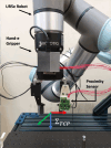
Experimental setup with ΣTCP frame.
FIGURE 6
FIGURE 6
(a) Software architecture for the teaching-by-demonstration use case. (b) Flowchart of the teaching-by-demonstration task.
FIGURE 7
FIGURE 7
(a) Indicator Itransly and commanded velocity uy . (b) Indicator Irotx and commanded velocity ωx .
FIGURE 8
FIGURE 8
Indicators and corresponding velocities during the teaching phase.
FIGURE 9
FIGURE 9
Operator guiding the robot by acting on the grasped electrical wire. From the starting point (a), the operator moves the robot along the y -axis (in green) by pulling the wire in the corresponding direction (b). The robot is then moved downward by pushing the wire down (c) and rotated anti-clockwise about the z -axis (in blue) (d). The robot is then translated again along the y -axis and rotated in the opposite direction (e, f). Finally, the robot end effector is translated and rotated to be positioned above the target clip (g), where the wire is then inserted (h).
FIGURE 10
FIGURE 10
Indicator Itransly during the autonomous wire routing.
FIGURE 11
FIGURE 11
Measured distance and commanded velocity during the collision avoidance experiment.
FIGURE 12
FIGURE 12
Collision avoidance involving two proximity sensor modules. The operator simulates obstacles on two sides of the end effector and the robot reacts by moving away from the operator’s hands.
FIGURE 13
FIGURE 13
Distance measured and commanded velocity during the user following experiment.
FIGURE 14
FIGURE 14
Hand guidance and obstacle avoidance. An operator guides the robot by pulling the grasped wire while another operator simulates an obstacle nearby the end effector. The robot reacts by following the operator guidance but moving far from the obstacle.
FIGURE 15
FIGURE 15
Measured distance, indicator, and velocities during the obstacle avoidance in hand guidance experiment.

References

    1. Caccavale R., Finzi A., Laudante G., Natale C., Pirozzi S., Villani L. (2023). Manipulation of boltlike fasteners through fingertip tactile perception in robotic assembly. IEEE/ASME Trans. Mechatronics 29, 820–831. 10.1109/TMECH.2023.3320519 - DOI
    1. Chandrasekaran B., Conrad J. M. (2015). “Human-robot collaboration: a survey,” in SoutheastCon 2015, 1–8. 10.1109/SECON.2015.7132964 - DOI
    1. Cichosz C., Gurocak H. (2022). “Collision avoidance in human-cobot work cell using proximity sensors and modified bug algorithm,” in 2022 10th international conference on control, mechatronics and automation (ICCMA), 53–59. 10.1109/ICCMA56665.2022.10011601 - DOI
    1. Cirillo A., Costanzo M., Laudante G., Pirozzi S. (2021a). Tactile sensors for parallel grippers: design and characterization. Sensors 21, 1915. 10.3390/s21051915 - DOI - PMC - PubMed
    1. Cirillo A., Laudante G., Pirozzi S. (2021b). Proximity sensor for thin wire recognition and manipulation. Machines 9, 188. 10.3390/machines9090188 - DOI

LinkOut - more resources