. 2025 Jun 19;25(12):3820.
doi: 10.3390/s25123820.

A Portable Insole System for Actively Controlled Offloading of Plantar Pressure for Diabetic Foot Care

Affiliations

A Portable Insole System for Actively Controlled Offloading of Plantar Pressure for Diabetic Foot Care

Pedro Castro-Martins et al. Sensors (Basel). .

Abstract

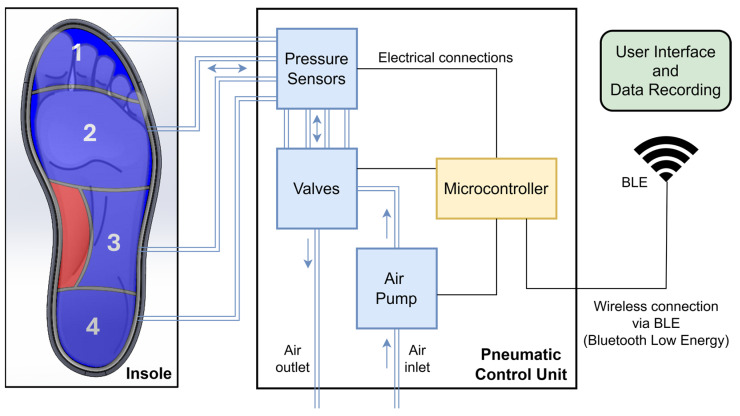
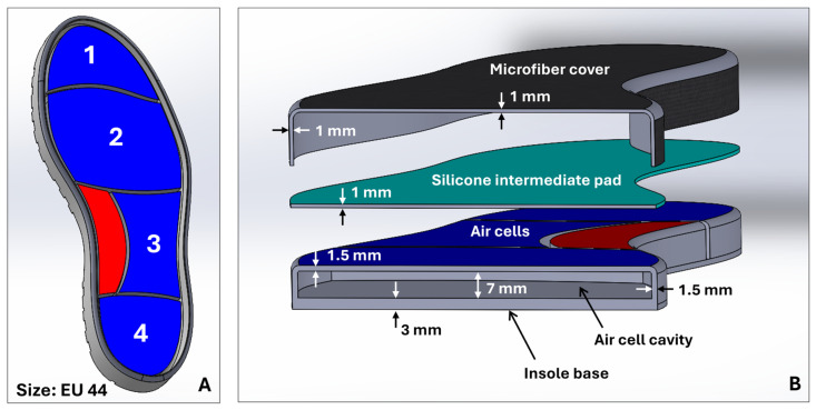
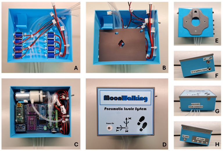
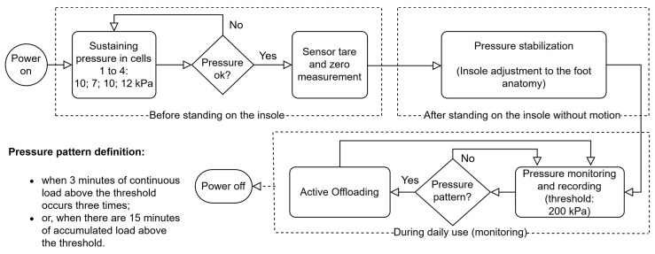
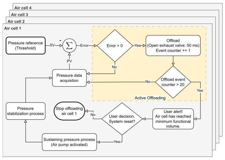
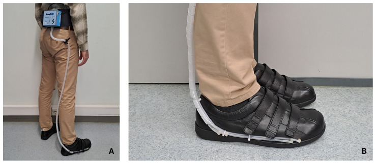
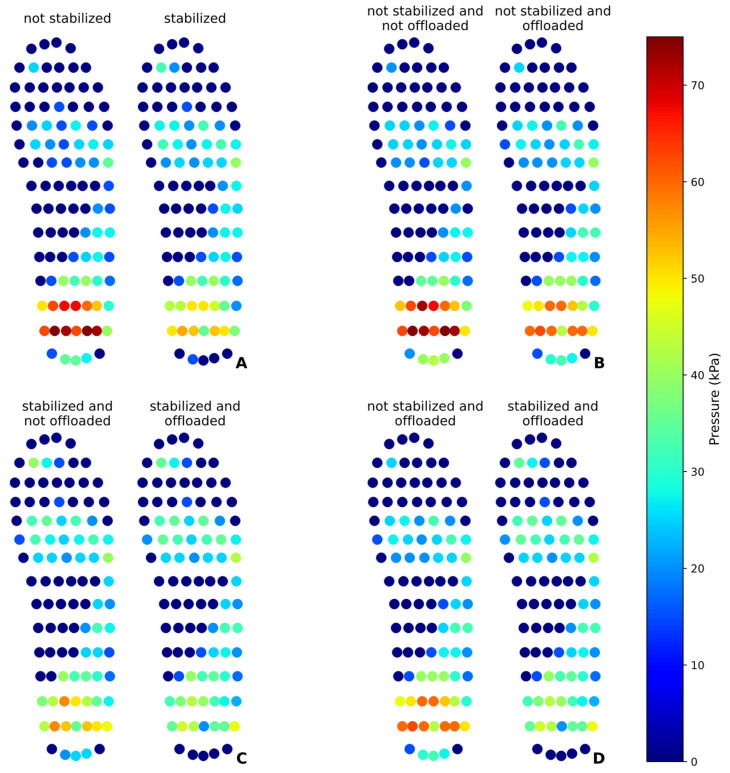
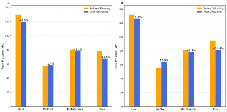
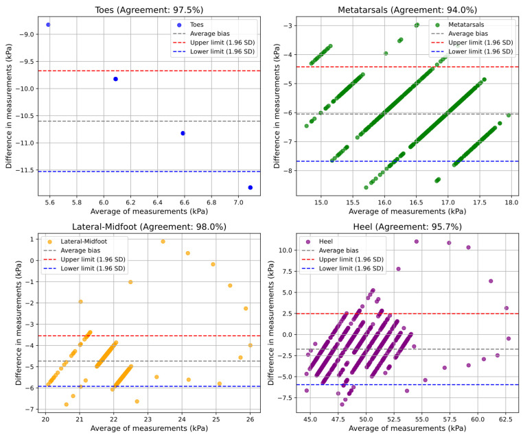
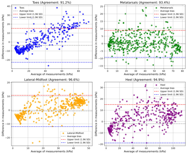
Plantar pressure monitoring is decisive in injury prevention, especially in at-risk populations such as people with diabetic foot. In this context, innovative solutions such as pneumatic insoles can be essential in plantar pressure management. This study describes the development of a variable pressure system that promotes the monitoring, stabilization, and offloading of plantar pressure through a pneumatic insole. This research was also intended to evaluate its ability to redistribute plantar pressure, reduce peak pressure in both static and dynamic conditions, and validate its pressure measurements by comparing the results with those obtained from a pedar® insole. Tests were carried out under both static and dynamic conditions, before and after the pressure stabilization process by air cells and the subsequent pressure offloading. During the validation process, methods were used to evaluate the agreement between measurements obtained by the two systems. The results of the static test showed that pressure stabilization reduced pressure on the heel by 32.43%, distributing it to the metatarsals and toes. After heel pressure offloading, the reduction reached 42.72%. In the dynamic test, despite natural dispersion of the measurements, a trend to reduce the peak pressure in the heel, metatarsals, and toes was observed. Agreement analysis recorded 96.32% in the static test and 94.02% in the dynamic test. The pneumatic insole proved effective in redistributing and reducing plantar pressure, with more evident effects in the static test. Its agreement with the pedar® system reinforces its reliability as a tool for measuring and managing plantar pressure, representing a promising solution for preventing plantar lesions.

Keywords: diabetic foot; health and safety; offloading; plantar pressure; pneumatic insole; ulcers; wearable sensors.


Conflict of interest statement

The authors declare no conflicts of interest. The funders had no role in the design of the study; in the collection, analyses, or interpretation of data; in the writing of the manuscript; or in the decision to publish the results.

Figures

Figure 1
Figure 1
Representative scheme of the variable pressure system. Configuration of the insole air cells in the plantar region of the foot: 1—toes (cell 1); 2—metatarsals (cell 2); 3—lateral-midfoot (cell 3); 4—heel (cell 4); red zone—medial-midfoot (without cell).
Figure 2
Figure 2
(A) Sole concept with layout of the air cells (numbered 1 to 4); (B) geometric characteristics of the air cell walls of the insole, silicone intermediate pad, and microfiber upper lining.
Figure 3
Figure 3
(A) Components that make up the pneumatic insole: (a) microfiber, (b) silicone intermediate pad, (c) rubber structure with air cells, and (d) connection points to pneumatic tubes; (B) pneumatic insole already inserted into a shoe (Ortomedical, Doctor Karl, EU44) and with the pneumatic connections.
Figure 4
Figure 4
Printed circuit board for control electronics, consisting of: (A) microcontroller; (B) integrated circuit with power transistors; (C) BLE module; (D) pressure sensors; (E) IMU module; (F) I2C multiplexer for communication with peripherals; (G) connector bar.
Figure 5
Figure 5
Assembly process of the pneumatic control unit: (A) Solenoid valves with derivations and connection to silicone tubes; (B) insulation between PCB and solenoid valves; (C) PCB, air pump and connections; (D) front view of the closed box; (E) rear view with waist fastening clip; (F) right side view with battery connector and switch; (G) lower view with connecting tubes to the insole; (H) left side view with one inlet and four air outlets.
Figure 6
Figure 6
Variable pressure system operation algorithm based on a critical pressure threshold.
Figure 7
Figure 7
Independent control loop for each air cell pressure regulation (represented by overlaid squares). The pressure reference is based on clinical guidelines, but it can be independently adjusted and personalized for each foot or patient condition. SV, setpoint value; PV, process value.
Figure 8
Figure 8
User equipped with the variable pressure system: (A) pneumatic control unit attached to the waist; (B) final appearance of the shoe (Ortomedical, Doctor Karl, EU44) with pneumatic insole.
Figure 9
Figure 9
Layout of the pedar® insole sensors superimposed on the pneumatic insole and corresponding to the regions of the foot defined by the air cells. Toes (zone 1): sensors 83 to 99; metatarsals (zone 2): sensors 48 to 82; lateral-midfoot (zone 3): sensors 22 to 26, 30 to 33, 37 to 40, and 43 to 47; Heel (zone 4): sensors 1 to 19.
Figure 10
Figure 10
Interface pressure (IP) maps at a time before and after each intervention of the pneumatic insole in the heel region in static mode: (A) effect of pressure stabilization; (B) effect of pressure offloading without stabilization; (C) effect of pressure offloading, previously stabilized; (D) effect of stabilization on the pressure offloading process.
Figure 11
Figure 11
Intensity of plantar peak pressures before and after the heel pressure offloading event, with the percentage recording of their effect on the different regions of the foot in the dynamic test: (A) without prior stabilization procedure; (B) with prior stabilization.
Figure 12
Figure 12
Agreement level evaluation of plantar pressure measurements obtained with the pneumatic insole (pedar® vs. pneumatic insole) during the static test conditions.
Figure 13
Figure 13
Agreement level evaluation of plantar pressure measurements obtained with pneumatic insole (pedar® vs. pneumatic insole) during the dynamic test conditions.

Similar articles

References

    1. Takahashi K.Z., Krupenevich R.L., Lenz A.L., Kelly L.A., Rainbow M.J., Franz J.R. Mechanics and Energetics of Human Feet: A Contemporary Perspective for Understanding Mobility Impairments in Older Adults. Biomechanics. 2022;2:494–499. doi: 10.3390/biomechanics2040038. - DOI - PMC - PubMed
    1. Jiang X., Napier C., Hannigan B., Eng J.J., Menon C. Estimating Vertical Ground Reaction Force during Walking Using a Single Inertial Sensor. Sensors. 2020;20:4345. doi: 10.3390/s20154345. - DOI - PMC - PubMed
    1. International Diabetes Federation . IDF Diabetes Atlas. 10th ed. International Diabetes Federation; Brussels, Belgium: 2021.
    1. Schaper N.C., van Netten J.J., Apelqvist J., Bus S.A., Fitridge R., Game F., Monteiro-Soares M., Senneville E., on behalf of the IWGDF Editorial Board Practical guidelines on the prevention and management of diabetes-related foot disease (IWGDF 2023 update) Diabetes Metab. Res. Rev. 2024;40:e3657. doi: 10.1002/dmrr.3657. - DOI - PubMed
    1. Castro-Martins P., Marques A., Coelho L., Vaz M., Costa J.T. Plantar pressure thresholds as a strategy to prevent diabetic foot ulcers: A systematic review. Heliyon. 2024;10:e26161. doi: 10.1016/j.heliyon.2024.e26161. - DOI - PMC - PubMed

LinkOut - more resources