

Utilizing Excess Resin in Prepregs to Achieve Good Performance in Joining Hybrid Materials
- PMID: 40574217
- PMCID: PMC12196891
- DOI: 10.3390/polym17121689
Utilizing Excess Resin in Prepregs to Achieve Good Performance in Joining Hybrid Materials
Abstract
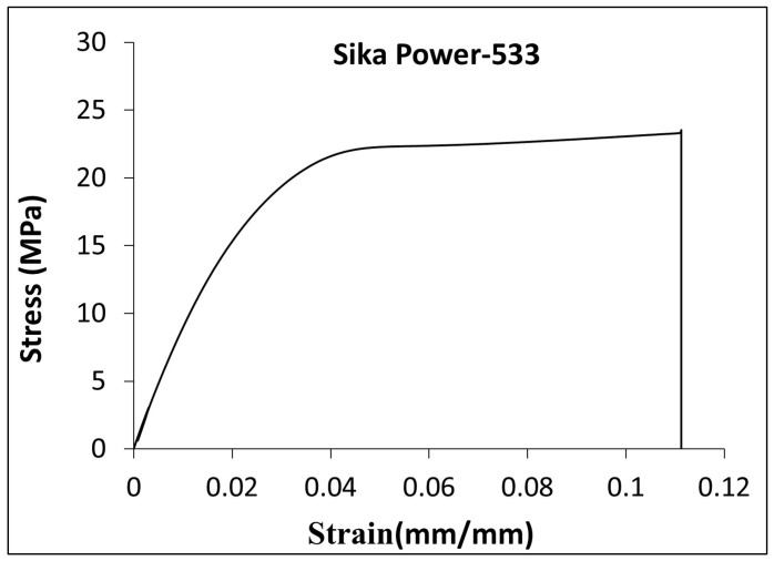
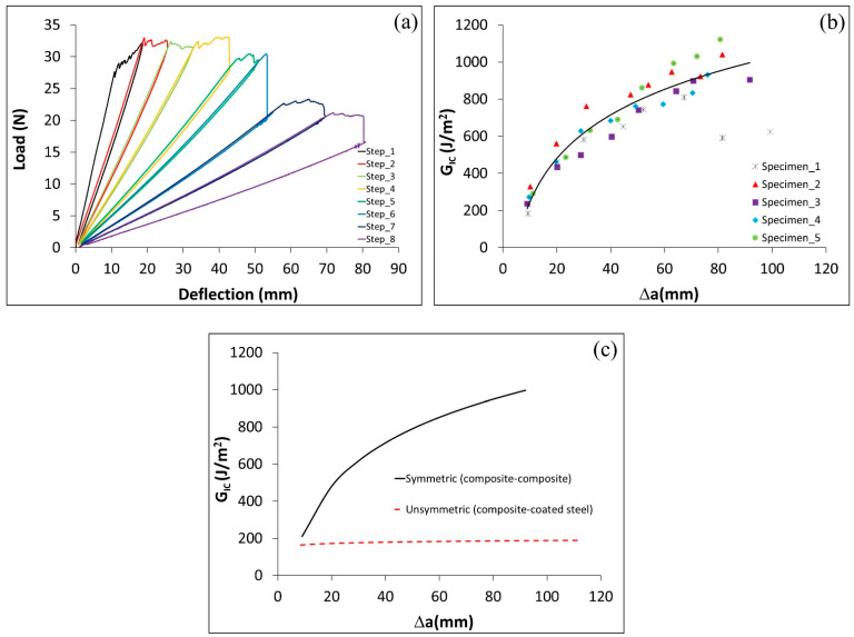
This study investigates the fracture toughness of adhesive joints between carbon fiber-reinforced polymer composites (CFRP) and boron-alloyed high-strength steel under Mode I and II loading, based on linear elastic fracture mechanics (LEFM). Two adhesive types were examined: the excess resin from the prepreg composite, forming a thin layer, and a toughened structural epoxy (Sika Power-533), designed for the automotive industry, forming a thick layer. Modified double cantilever beam (DCB) and end-notched flexure (ENF) specimens were used for testing. The results show that using Sika Power-533 increases the critical energy release rate by up to 30 times compared to the prepreg resin, highlighting the impact of adhesive layer thickness. Joints with the thick Sika adhesive performed similarly regardless of whether uncoated or Al-Si-coated steel was used, indicating the composite/Sika interface as the failure point. In contrast, the thin resin adhesive layer exhibited poor bonding with uncoated steel, which detached during sample preparation. This suggests that, for thin layers, the resin/steel interface is the weakest link. These findings underline the importance of adhesive selection and layer thickness for optimizing joint performance in composite-metal hybrid structures.
Keywords: Al–Si-coated boron steel; adhesive layer thickness; double cantilever beam; epoxy adhesives; metal–composite adhesive joints.
Conflict of interest statement
The authors declare no conflict of interest.
Figures


References
-
- Li X., Guan Z., Li Z., Liu L. A new stress-based multi-scale failure criterion of composites and its validation in open hole tension tests. Chin. J. Aeronaut. 2014;27:1430–1441. doi: 10.1016/j.cja.2014.10.009. - DOI
-
- Banea M.D., da Silva L.F.M. Adhesively bonded joints in composite materials: An overview. Proc. Inst. Mech. Eng. Part L J. Mater. Des. Appl. 2009;223:1–18. doi: 10.1243/14644207JMDA219. - DOI
-
- Kim K.-S., Yi Y.-M., Cho G.-R., Kim C.-G. Failure prediction and strength improvement of uni-directional composite single lap bonded joints. Compos. Struct. 2008;82:513–520. doi: 10.1016/j.compstruct.2007.02.005. - DOI
-
- Baker A.A., Jones R. Bonded Repair of Aircraft Structures. Martinus Nijhoff Publishers; Dordrecht, The Netherlands: 1988.
-
- Floros I.S., Tserpes K.I., Löbel T. Mode-I, mode-II and mixed-mode I+II fracture behavior of composite bonded joints: Experimental characterization and numerical simulation. Compos. B Eng. 2015;78:459–468. doi: 10.1016/j.compositesb.2015.04.006. - DOI
LinkOut - more resources
Full Text Sources
