. 2025 Jul 1;16(1):5551.
doi: 10.1038/s41467-025-61271-6.

Highly ordered clustering of TNFα and BAFF ligand-receptor-intracellular adaptor complexes on a lipid membrane

Affiliations

Highly ordered clustering of TNFα and BAFF ligand-receptor-intracellular adaptor complexes on a lipid membrane

Chan Seok Lim et al. Nat Commun. .

Abstract

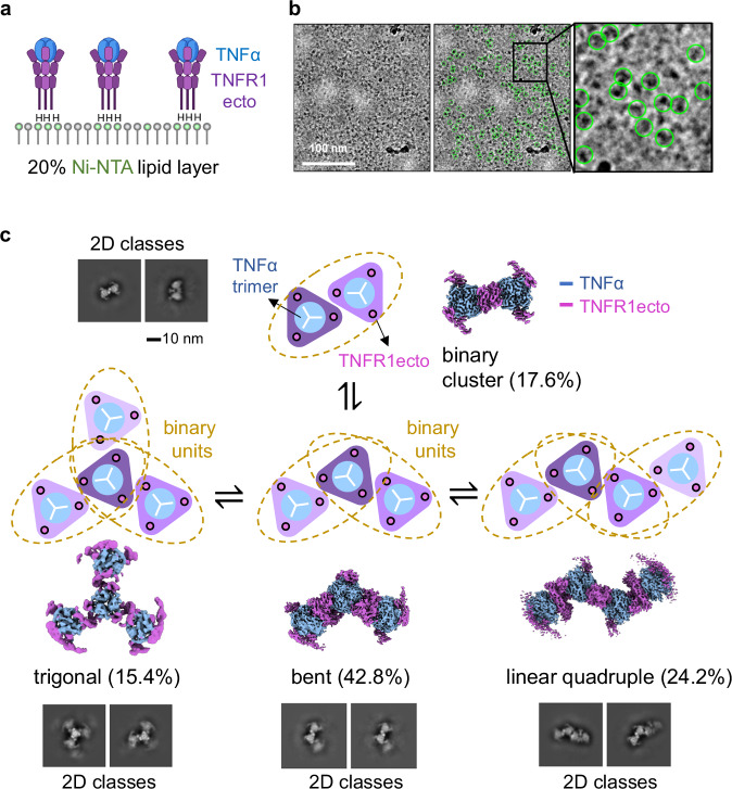
The TNF family plays a critical role in immune regulation. Here, we present high-resolution structures of clusters formed by two TNF receptor family proteins, TNFR1 and BAFFR. Using a lipid monolayer method to mimic their membrane-bound state, we observe that the TNFα-TNFR1 complex forms highly ordered clusters of trimers on the lipid membrane. A non-competitive TNFR1 antagonist that inhibits receptor activation disrupted these clusters without blocking ligand binding or receptor trimerization. Furthermore, we find that the BAFF-BAFFR, BAFF-TACI, and BAFF-BCMA receptor-ligand complexes predominantly form pentagonal clusters of trimers on the lipid membrane. Notably, the binding of the intracellular adaptor TRAF3 to the BAFF-BAFFR complex induces a structural transition from a pentagonal to a flat hexagonal cluster. Mutations in BAFF that impair BAFFR activation prevented cluster formation. Our findings demonstrate that ligand binding induces the formation of highly ordered clusters of TNFR1 and BAFFR receptors on the lipid membrane, which is essential for their activation.


Conflict of interest statement

Competing interests: The authors declare no competing interests.

Figures

Fig. 1
Fig. 1. The TNFα-TNFR1ecto complex forms ordered clusters on the lipid layer.
a An octa-histidine tag was attached to the C-terminus of TNFR1ecto, allowing the TNFα-TNFR1ecto complex to bind to the Ni-NTA lipid monolayer. The head groups of Ni-NTA lipids are indicated in green. “H” denotes the octa-histidine tag. Created in BioRender. Lim, C. (2025) https://BioRender.com/z6b5t4x. b A representative (n = 2,538) cryo-electron microscopy (cryo-EM) image of the TNFα-TNFR1ecto complex (left). Protein particles used for structure determination are highlighted with green circles (middle and right panels). c 2D class averages (left), a schematic diagram (middle), and a 3D refined map (right) of the binary cluster. Below are schematic diagrams, 3D refined maps, and 2D class averages of higher-order clusters formed by the assembly of the binary cluster units indicated by dashed orange circles. The proportion of protein particles belonging to each cluster is indicated in parentheses. The lipid layer consisted of 20% DGS-NTA(Ni²⁺) and 80% POPC.
Fig. 2
Fig. 2. Structures of the binary clusters of the TNFα-TNFR1ecto and TNFα-TNFR1fl complexes.
a Cryo-EM electron density map (left) and overall structure (right) of the binary cluster of the TNFα-TNFR1ecto complex. TNFα is colored blue, while TNFR1ecto in trimer 1 is dark purple and in trimer 2 is light purple. b The two TNFα-TNFR1ecto trimers are twisted by 63.7° when viewed from the side. c Tethering of the TNFα-TNFR1fl complex to the Ni-NTA lipid monolayer. A hexa-histidine tag was attached to the C-terminus of TNFα. Detergent belts are schematically represented in gray and purple. The head groups of Ni-NTA lipids are indicated in green. “H” denotes the histidine tag. Created in BioRender. Lim, C. (2025) https://BioRender.com/z6b5t4x. d Cryo-EM electron density map of the binary cluster of the TNFα-TNFR1fl complex. TNFα is colored blue, while TNFR1ecto in trimer 1 is dark purple and in trimer 2 is light purple. e Structural comparison of the binary clusters of the TNFα-TNFR1ecto and TNFα-TNFR1fl complexes. The TNFα-TNFR1ecto complex is shown in gray, while TNFα and TNFR1fl in the TNFα-TNFR1fl complex are colored blue and purple, respectively.
Fig. 3
Fig. 3. The DOM1h-574-208 nanobody disrupts the ordered binary cluster of the TNFα-TNFR1ecto complex.
a Composite electron density map of the TNFα-TNFR1ecto-DOM1h nanobody complex in solution. TNFα, TNFR1ecto, and DOM1h are shown in blue, purple, and red, respectively. Focused refinement was performed on one of the three DOM1h nanobody regions in the map, after which maps for the remaining two nanobodies were generated by applying threefold symmetry. b Representative (n = 6408) image (left) and 2D class averages (middle) of the TNFα-TNFR1ecto-DOM1h nanobody complex in solution. The electron densities correspond to the bound nanobodies are highlighted with dashed red circles on the right panel. c Representative (n = 634) image (left) and 2D class averages (middle) of the TNFα-TNFR1ecto-DOM1h nanobody complex bound to the lipid monolayer. The proportion of protein particles belonging to each cluster is indicated in parentheses. The electron densities correspond to the bound nanobodies are highlighted with dashed red circles on the right panel. d Cryo-EM electron density map of the distorted binary cluster of the TNFα-TNFR1ecto-DOM1h nanobody complex bound to the Ni-NTA lipid layer. TNFα and TNFR1ecto are shown in blue and purple, respectively. e Superimposition of TNFR1ecto structures. TNFR1ecto in the ordered TNFα-TNFR1ecto binary cluster, the crystal structure, and the distorted TNFα-TNFR1ecto-DOM1h binary cluster are shown in purple, gray, and red, respectively.
Fig. 4
Fig. 4. The BAFF-BAFFRecto complex forms ordered clusters on the lipid layer.
a An octa-histidine tag was attached to the C-terminus of BAFFRecto, allowing the BAFF-BAFFRecto complex to bind to the Ni-NTA lipid monolayer. A representative (n = 1464) cryo-EM image (upper right) and 2D class averages (lower three panels) of the clusters are shown. The proportion of protein particles belonging to each cluster is written above the 2D class images. The head groups of Ni-NTA lipids are indicated in green. “H” denotes the histidine tag. Created in BioRender. Lim, C. (2025) https://BioRender.com/z6b5t4x. b Cryo-EM electron density map of the BAFF-BAFFRecto pentagonal cluster. BAFF and BAFFRecto are colored blue and orange, respectively. c A hexa-histidine tag was attached to the N-terminus of BAFF, enabling the BAFF-BAFFRfl complex to bind to the Ni-NTA lipid monolayer. Created in BioRender. Lim, C. (2025) https://BioRender.com/z6b5t4x. d Cryo-EM map of the pentagonal BAFF-BAFFRfl cluster. The maps for the BAFF and BAFFRfl proteins are colored blue and orange, respectively. The view is the same as in the upper panel of (b). e Cryo-EM maps of the BAFF-BAFFRfl cluster. The lower and higher contour level maps are colored gray and blue/orange, respectively. f Structural comparison of the pentagonal BAFF-BAFFRecto and BAFF-BAFFRfl clusters. The BAFF-BAFFRecto structure is shown in gray, while BAFF and BAFFRfl in the BAFF-BAFFRfl cluster are colored blue and orange, respectively.
Fig. 5
Fig. 5. Cryo-EM structure of the BAFF-BCMAecto complex.
a Representative (n = 1,571) cryo-EM micrograph (left) and 2D class averages (right) of the BAFF-BCMAecto complex. Protein particles selected for 3D map reconstruction are highlighted with green circles (middle panel). b 3D reconstructed map of the BAFF-BCMAecto complex, with an estimated resolution of 2.5 Å. The BAFF and BCMAecto maps are colored blue and orange, respectively. c 3D cryo-EM density map of the BAFF-BCMAecto complex. The structure of the BAFF cluster extracted from the pentagonal BAFF-BAFFRecto cluster is fitted into the map. The structure and density map are colored blue and gray, respectively. The BCMAecto structures are not shown.
Fig. 6
Fig. 6. Cryo-EM structure of the BAFF-TACIecto complex.
a Representative (n = 5302) cryo-EM micrograph (left) and 2D class averages (right) of the BAFF-TACIecto complex. Protein particles selected for 3D map reconstruction are highlighted with green circles (middle panel). b 3D reconstructed map of the BAFF-TACIecto complex, with an estimated resolution of 2.9 Å. The BAFF and TACIecto maps are colored blue and orange, respectively. c 3D cryo-EM density map of the BAFF-TACIecto complex. The structure of the BAFF cluster extracted from the pentagonal BAFF-BAFFRecto cluster is fitted into the map. The structure and density map are colored blue and gray, respectively. The TACIecto structures are not shown.
Fig. 7
Fig. 7. Mutations in the “flap” region of BAFF disrupt BAFF-BAFFRecto clusters.
a Close-up view of the BAFF clustering interface in the BAFF-BAFFR pentagonal cluster. BAFF and BAFFR proteins are shown in gray and orange, respectively. Two BAFF proteins involved in clustering interactions are highlighted in light and dark blue, with a zoomed-in view provided in the right panel. Oxygen and nitrogen atoms in the side chains are colored red and dark blue, respectively. Residue numbers for BAFF and BAFFR in the second BAFF trimer are indicated with apostrophes. b Representative cryo-EM images (upper) and 2D class averages (lower three panels) of mutant BAFF-BAFFRecto complexes. Representative micrographs are from n = 816 (K216R), n = 628 (H218A) and n = 581 (E223K) cryo-EM experiment sets, respectively. c Histogram showing the proportions of each cluster in wild-type and mutant BAFF-BAFFRecto complexes.
Fig. 8
Fig. 8. Clustered structures of the BAFF-BAFFRfl-TRAF3 complexes.
a A hexa-histidine tag was attached to the N-terminus of BAFF, allowing the hisBAFF-BAFFRfl-TRAF3 complex to bind to the Ni-NTA lipid monolayer. The head groups of Ni-NTA lipids are indicated in green. “H” denotes the histidine tag. Created in BioRender. Lim, C. (2025) https://BioRender.com/z6b5t4x. b Bottom view and c side view of the cryo-EM map of the hisBAFF-BAFFRfl-TRAF3 cluster. The BAFFR intracellular domain and TRAF3 proteins are colored orange and blue, respectively. Alpha helical rods from the second TRAF3 cluster are shown in gray. Focused refinement of the TRAF3 cluster region was performed for 3D map reconstruction. d Side view of the cryo-EM map of the hisBAFF-BAFFRfl-TRAF3 cluster without the focused refinement of the TRAF3 region. The structures of BAFF, BAFFR, and TRAF3 are fitted into the map. The map, BAFF, BAFFR, and TRAF3 proteins are shown in gray, green, orange, and blue, respectively. Due to structural flexibility, only part of the TRAF3 coiled-coil helices are visible. The missing segments of the TRAF3 coiled-coil helices were predicted using AlphaFold3. e Top view of the cryo-EM map of the hisBAFF- BAFFRfl-TRAF3 cluster without focused refinement. The map corresponding to the extracellular side of the hisBAFF-BAFFR-TRAF3 cluster is shown in light cyan. The structures of three BAFF-BAFFRecto trimers are fitted into the map. f An octa-histidine tag was attached to the N-terminus of TRAF3, allowing the BAFF-BAFFRfl-hisTRAF3 complex to bind to the Ni-NTA lipid monolayer. The head groups of Ni-NTA lipids are indicated in green. “H” denotes the histidine tag. Created in BioRender. Lim, C. (2025) https://BioRender.com/z6b5t4x. g Top view and h side view of the electron density map of the BAFF-BAFFRfl-hisTRAF3 cluster. The BAFFR intracellular domain and TRAF3 are colored orange and blue, respectively.
Fig. 9
Fig. 9. Close-up view of the hisBAFF-BAFFR-TRAF3 cluster and the proposed model of BAFFR activation.
a Assembly of the three hisBAFF-BAFFRfl-TRAF3 trimers within the cluster is shown. TRAF3 and the BAFFR intracellular domain are colored in a blue gradient and orange, respectively. A clustering interface formed by TRAF3 and the BAFFR intracellular domain is highlighted with a dashed red box and enlarged in (b). b Close-up view of the clustering interface. Residue numbers for the second TRAF3 trimer are indicated with an apostrophe, while residue numbers for the BAFFR intracellular domain are shown in orange and marked with a double apostrophe. Sulfur, nitrogen, and oxygen atoms in the side chains are colored yellow, blue, and red, respectively. c Proposed model for BAFFR activation by BAFF. BAFF, BAFFR, and TRAF3 are shown in green, orange, and blue, respectively. The plasma membrane is schematically drawn in gray. Created in BioRender. Lim, C. (2025) https://BioRender.com/z6b5t4x.

Similar articles

References

    1. Kucka, K. & Wajant, H. Receptor oligomerization and its relevance for signaling by receptors of the tumor necrosis factor receptor superfamily. Front. Cell Dev. Biol.8, 615141 (2020). - PMC - PubMed
    1. Dostert, C., Grusdat, M., Letellier, E. & Brenner, D. The TNF family of ligands and receptors: communication modules in the immune system and beyond. Physiol. Rev.99, 115–160 (2019). - PubMed
    1. Wallach, D. The tumor necrosis factor family: family conventions and private idiosyncrasies. Cold Spring Harb. Perspect. Biol. 10, a028431 (2018). - PMC - PubMed
    1. Croft, M., Benedict, C. A. & Ware, C. F. Clinical targeting of the TNF and TNFR superfamilies. Nat. Rev. Drug Discov.12, 147–168 (2013). - PMC - PubMed
    1. Abitbol, V., Benkhalifa, S., Habauzit, C. & Marotte, H. Navigating adalimumab biosimilars: an expert opinion. J. Comp. Eff. Res.12, e230117 (2023). - PMC - PubMed

MeSH terms

Substances

LinkOut - more resources