

Impact of layer count and thickness on spin wave modes in multilayer synthetic antiferromagnets
- PMID: 40596545
- PMCID: PMC12219261
- DOI: 10.1038/s41598-025-08393-5
Impact of layer count and thickness on spin wave modes in multilayer synthetic antiferromagnets
Abstract
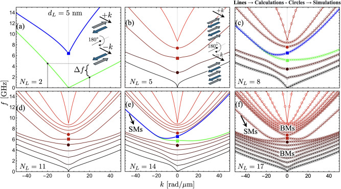
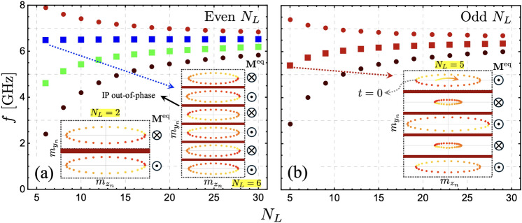
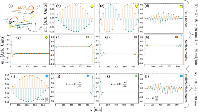
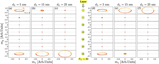
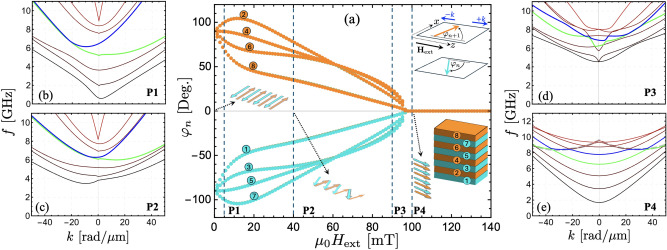
In this study, the spin-wave spectrum in multilayer synthetic antiferromagnets is calculated. The analysis focuses on the effects of varying both the thicknesses and the number of ferromagnetic layers within these structures. The results reveal that a non-reciprocal spin-wave dispersion occurs in structures with an even number of layers, while a reciprocal dispersion of two counterpropagating waves is observed for systems with an odd number of layers. As the number of layers and their thickness increase, the study identifies the distinctive presence of bulk and surface modes, with the latter being strongly affected by dynamic dipolar interactions. In multilayers with an even number of layers, such surface modes exhibit nonreciprocal behavior, maintaining their surface character only in one propagation direction. Conversely, in odd-layer systems, the symmetric counterpropagating surface modes have similar properties. Additionally, the bulk modes for both even and odd numbers of layers converge towards similar dynamic behavior as the thickness and number of layers increase. As the thickness of the ferromagnetic layers increases, the surface modes in multilayers with an odd number of layers remain localized at either the top or bottom, depending on the sign of the wave vector. In contrast, for the even case, the surface modes appear in both the top and bottom ferromagnetic layers when the layers are thin or ultrathin. However, as the ferromagnetic layer thickness increases, these modes gradually become predominantly localized at either the top or bottom of the multilayer. Finally, the study explores the application of an external magnetic field, demonstrating that surface chiral modes are absent in the saturated state, resulting in a reciprocal spin-wave dispersion. This establishes a magnetic field-mediated control over non-reciprocal localized surface modes.
© 2025. The Author(s).
Conflict of interest statement
Declarations. Competing interests: The authors declare no competing interests.
Figures


Similar articles
-
Psychological interventions for adults who have sexually offended or are at risk of offending.Cochrane Database Syst Rev. 2012 Dec 12;12(12):CD007507. doi: 10.1002/14651858.CD007507.pub2. Cochrane Database Syst Rev. 2012. PMID: 23235646 Free PMC article.
-
Systemic pharmacological treatments for chronic plaque psoriasis: a network meta-analysis.Cochrane Database Syst Rev. 2017 Dec 22;12(12):CD011535. doi: 10.1002/14651858.CD011535.pub2. Cochrane Database Syst Rev. 2017. Update in: Cochrane Database Syst Rev. 2020 Jan 9;1:CD011535. doi: 10.1002/14651858.CD011535.pub3. PMID: 29271481 Free PMC article. Updated.
-
Systemic pharmacological treatments for chronic plaque psoriasis: a network meta-analysis.Cochrane Database Syst Rev. 2021 Apr 19;4(4):CD011535. doi: 10.1002/14651858.CD011535.pub4. Cochrane Database Syst Rev. 2021. Update in: Cochrane Database Syst Rev. 2022 May 23;5:CD011535. doi: 10.1002/14651858.CD011535.pub5. PMID: 33871055 Free PMC article. Updated.
-
A rapid and systematic review of the clinical effectiveness and cost-effectiveness of paclitaxel, docetaxel, gemcitabine and vinorelbine in non-small-cell lung cancer.Health Technol Assess. 2001;5(32):1-195. doi: 10.3310/hta5320. Health Technol Assess. 2001. PMID: 12065068
-
Home treatment for mental health problems: a systematic review.Health Technol Assess. 2001;5(15):1-139. doi: 10.3310/hta5150. Health Technol Assess. 2001. PMID: 11532236
References
-
- Wang, K., Bheemarasetty, V. & Xiao, G. Spin textures in synthetic antiferromagnets: Challenges, opportunities, and future directions. APL Materials11 (2023).
-
- Grünberg, P., Schreiber, R., Pang, Y., Brodsky, M. & Sowers, H. Layered magnetic structures: Evidence for antiferromagnetic coupling of fe layers across cr interlayers. Physical review letters57, 2442 (1986). - PubMed
-
- Bruno, P. & Chappert, C. Ruderman-kittel theory of oscillatory interlayer exchange coupling. Physical Review B46, 261 (1992). - PubMed
-
- Fert, A., Grünberg, P., Barthélémy, A., Petroff, F. & Zinn, W. Layered magnetic structures: interlayer exchange coupling and giant magnetoresistance. Journal of Magnetism and Magnetic Materials140, 1–8 (1995).
Grants and funding
LinkOut - more resources
Full Text Sources
Research Materials
